General Specifications
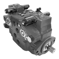
Design Axial piston pump of cradle swashplate design with variable displacement
Direction of rotation Clockwise, counterclockwise
Pipe connections Main pressure ports: ISO split flange boss
Remaining ports: SAE straight thread O-ring boss
Recommended installation position Pump installation position is discretionary, however the recommended control position is on the top
or at the side, with the top position preferred.
Vertical input shaft installation is acceptable.
If input shaft is at the top 1 bar case pressure must be maintained during operation.
The pump housing must be filled with hydraulic fluid under all conditions; including after a long
period of shutdown. Before operating the machine, ensure the pump housing and case drain lines are
free of air.
Recommended mounting for a multiple pump stack is to arrange the highest power flow towards the
input source.
Consult Danfoss for nonconformance to these guidelines.
Auxiliary cavity pressure Will be inlet pressure with internal charge pump. For reference see Operating Parameters. Will be case
pressure with external charge supply.
Please verify mating pump shaft seal capability.
Features and Options
Feature Unit Frame
042 055 075 100 130 180 250
Displacement cm³/rev.
[in³]/rev.
42
[2.56]
55
[3.35]
75
[4.59]
100
[6.10]
130
[7.93]
180
[10.98]
250
[15.25]
Flow at rated speed (theoretical) l/min.
[US gal/
min.]
176
[46]
215
[57]
270
[71]
330
[87]
403
[106]
468
[124]
575
[160]
Torque at maximum
displacement (theoretical)
N•m/bar
[lbf•in/1000
psi]
0.67
[410]
0.88
[530]
1.19
[730]
1.59
[970]
2.07
[1260]
2.87
[1750]
3.97
[2433]
Mass moment of inertia of
rotating components
kg•m²
[slug•ft²]
0.0023
[0.0017]
0.0060
[0.0044]
0.0096
[0.0071]
0.0150
[0.0111]
0.023
[0.0170]
0.0380
[0.0280]
0.0650
[0.0479]
Weight (with control opt. MA) kg [lb] 34 [75] 40 [88] 49 [108] 68 [150] 88 [195] 136 [300] 154 [340]
Mounting (per ISO 3019-1) Flange
102-2 (SAE B)
Flange
127-4 (SAE C)
Flange
152-4 (SAE D)
Flange
165-4 (SAE E)
Rotation Right hand or Left hand rotation
Main ports: 4-bolt split-flange
(per SAE J518 code 62)
mm
[in]
19.05
[0.75]
25.4
[1.0]
25.4
[1.0]
25.4
[1.0]
31.75
[1.25]
31.75
[1.25]
38.1
[1.5]
Main port configuration Twin port Twin or side port Twin port
Case drain ports (SAE O-ring
boss)
UNF thread
(in.)
0.875–14 1.0625–12 1.0625–12 1.0625–12 1.3125–12 1.625–12 1.625–12
Other ports SAE O-ring boss
Shafts Splined, and tapered shafts available
Auxiliary mounting SAE-A, B, C SAE-A, B, C, D SAE-A, B, C, D, E
Technical Information Series 90 Axial Piston Pumps
Technical Specifications
8 520L0603 • Rev 0804 • March 2016