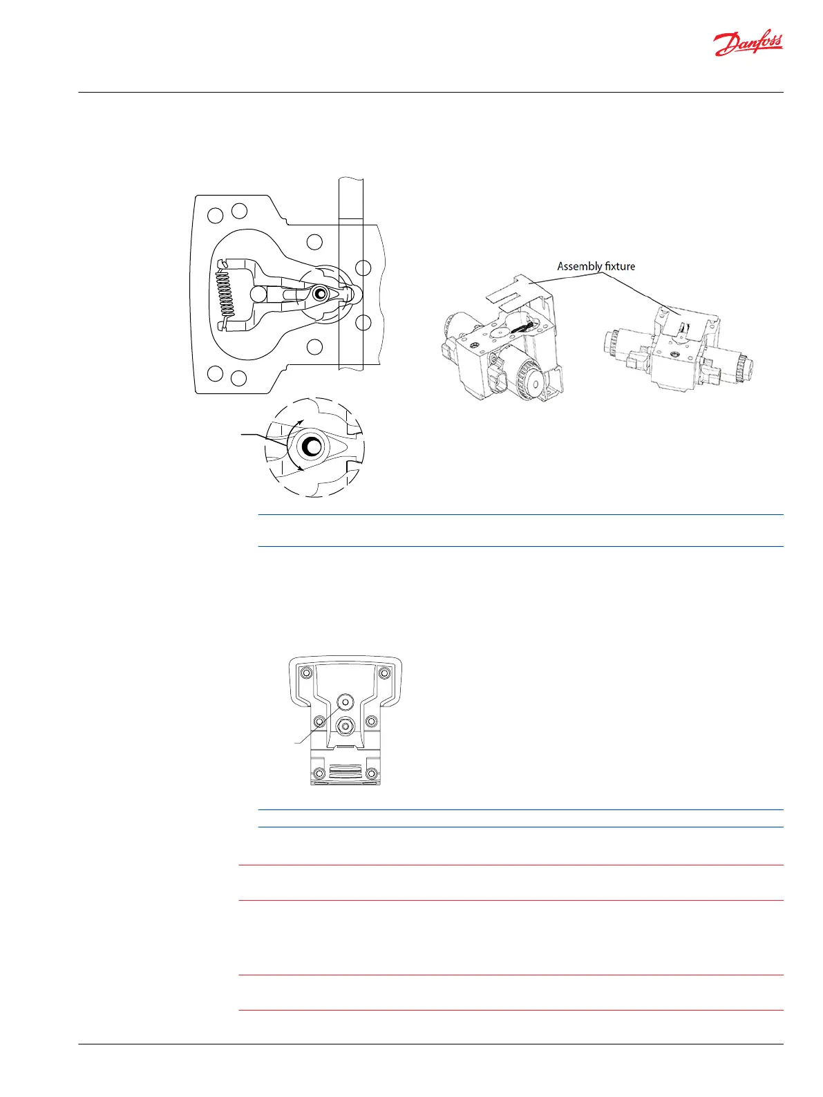
7. Pull assembly fixture out before installing control screws.
Solenoid shaft
Feedback pin
Adjusting
screw
(cam)
Maximum
adjustment
less than 120°
Control spool
Remove plug (D065) and verify the swashplate feedback pin is properly positioned between control
feedback arms.
8. Install the control module and six cap screws (D250).
9. Using a 5 mm internal hex wrench, fasten control to pump with screws (D250).
10. Torque screws to 13.3 N•m [9.8 lbf•ft] following torque sequence shown.
1
2
3
6
5
4
Torque sequence
(6 screw control)
D065
For proper neutral adjustment procedure, refer to Control Neutral Adjustment on page 38 topic.
Warning
Calibration of sensor output in vehicle software is mandatory after sensor replacement because output
signal can vary from one sensor to the other.
Automotive Control Repair
Drain pump completely before removing control.
Possible erratic pump operation.
Do not allow metal fragments to fall into control housing. Do not fail to install screen.
Service Manual
H1P 069—H1P 250 Axial Piston Single Pumps
Minor Repair
©
Danfoss | September 2020 AX152886482551en-000504 | 49

 Loading...