43
180R9267 / IOM APP 1.5-3.5 Appendices - v04 / 11.2013
Instruction Trouble shooting guide for APP and APP S 674 pumps
4
06.2013
1. No ow/no pressure
Cause Remedy Comments
1.1 Dry running
(no water supply to the pump)
If no water comes out of the pump:
1.1.1 Check that inlet valve is open.
1.1.2 Check that booster pump is running.
Mount a low pressure switch in front of the
pump and check its set point/ function. The low
pressure switch ensures that the pump does
not start until the inlet pressure has reached-
minimum inlet pressure (see User manual).
1.2 Pump reversing
(electric motor is running the wrong direction,
i.e. counter-clockwise)
1.2.1 Change the phase on the electric motor to
make it run clockwise.
WARNING:
- The pump must not run without water for
more than a few seconds.
- If the pump takes in water from the high-
pressure outlet line, it builds up pressure in
pump housing and will eventually break
down.
Rotation direction for the APP or APP S 674
pump is shown by an arrow on the label on the
pump.
1.3 No rotation of electric motor 1.3.1 Check that main switch is switched on.
1.3.2 Check the electricity at the facility.
1.3.3 Ensure that motor relay is switched on.
1.3.4 Ensure that fuse is not blown.
1.3.5 Ensure that booster pump is started.
1.3.6 Check that the monitor switches are
working correctly.
1.3.7 Disconnect pump from electric motor and
check that the motor is capable of running
with no load.
If motor-type relay or the electrical fuse is
blown, check that electric motor is sized
correctly.
1.4 No rotation of pump 1.4.1 Ensure that coupling between electric
motor and pump is connected.
1.4.2 Check if coupling is damaged.
1.4.3 Check that electric motor is sized correctly.
1.4.4 Check that the electrical installation is
correctly sized.
1.4.5 Contact Danfoss Sales oce for guidelines
in how to troubleshoot internal pump
parts.
1.5 Axial load on pump shaft
(may cause high internal leakage)
Only applying to
APP 0.6 to APP 3.5 and
APP 21 to APP 26 only.
Also applying to APP S 674 pumps.
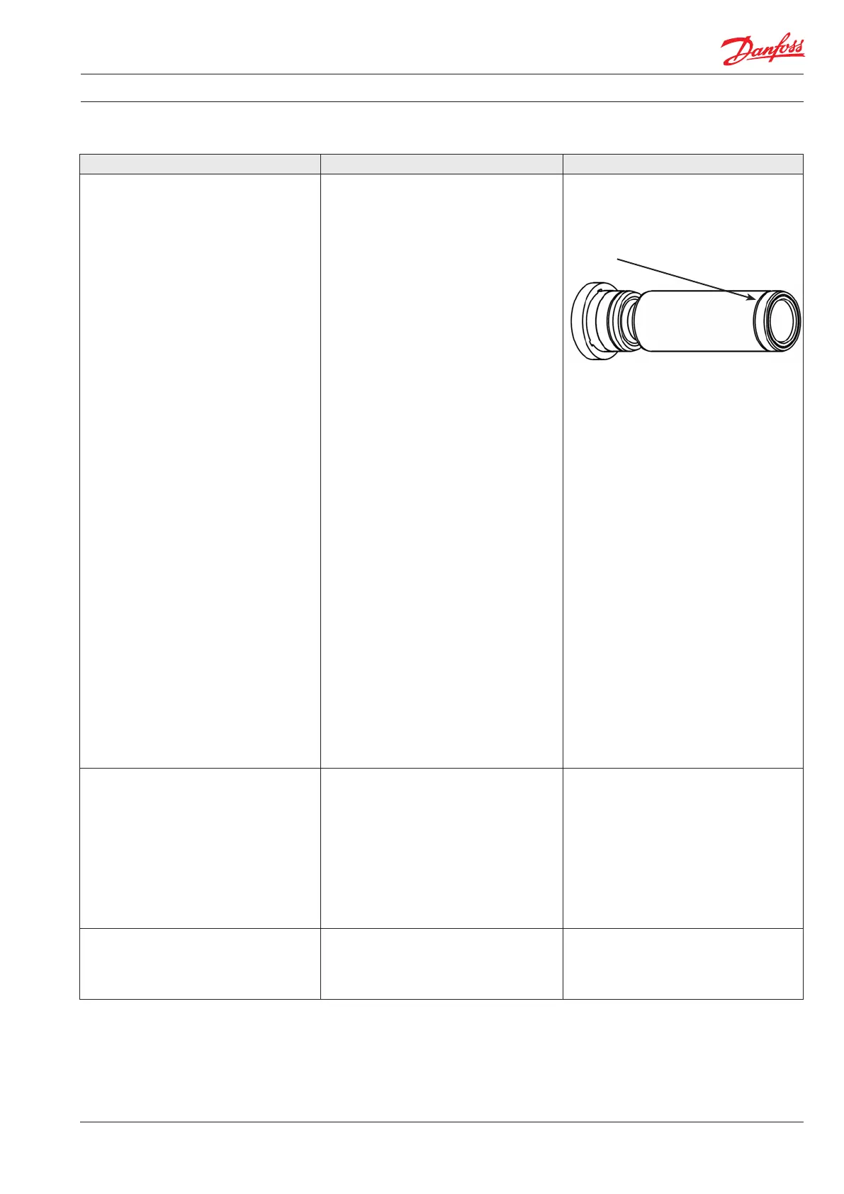
1.5.1 Ensure that the air gap between the two
coupling parts is min 5 mm. It should
always be possible to move the plastic part
on the coupling at least 3 mm.
To ensure easy mounting of the exible
coupling without using tools, the tolerances
must be dimensioned accordingly.
WARNING:
Any axial and/or radial loads on the shaft
must be avoided. Any axial or radial load will
cause breakdown.
1.6 Pump damage
(the internal parts may be damaged)
1.6.1 Contact Danfoss sales oce for guidelines
in how to troubleshoot internal pump
parts.
Instructions on internal elements
180R9092/180R9085 for APP 0.6-1.0
180R9091/180R9147/180R9089 for APP 1.5-3.5
180R9093/180R9090 for APP 5.1-10.2
180R9228/180R9227 for APP 11-13 and APP 16-22
180R9121/180R9139 for APP 21-43
180R9281 for APP S 674 3.0-3.5
180R9280 for APP S 674 5.1-9.0
180R9278 for APP S 674 21-38
– are available on www.ro-solutions.com.
A B C
A - Bell housing
B - Flexible coupling
C - Motor shaft
Instruction Trouble shooting guide for APP and APP S 674 pumps
Cause Remedy Comments
2.1 Wear on pump
Large internal leakage due to:
-
2.1.1 Dismantle the pump.
2.1.2 Check valve plate.
Valve plate has marks/scratches on the
surface facing the port plate. Minor wear
on valve plate can cause large internal
leakage. See Index 6.1.
2.1.3 Check port plate.
Port plate has marks/scratches on the
surface facing the valve plate. Minor wear
on port plate can cause large internal
leakage. See Index 6.2.
2.1.4 Check cylinder barrel.
Liners in cylinder barrel may be scratched
or worn. Insert a piston in the liner and
check the t. If there is any space
(clearance) between liner and piston, liner
or piston is worn.
2.1.5 Pre-treatment
Analyse uid for content of particles.
- Check that lters are OK and working
correctly.
2.1.6 Main ltration
Check that the correct lter type is used
(particles in uid must not exceed 10 μm).
Danfoss High Pressure Pumps supplies
lters, please contact the sales oce.
2.1.7 Fluid type
The APP and APP S 674 pumps are designed
for seawater operation; for any other uid,
please contact Danfoss High Pressure
Pumps sales oce for further help.
2.1.8 High uid temperature
If uid temperature is above 50°C, stop the
pump immediately.
- Check internal parts (see above).
Typical signs of wear:
Polished surface all over the swash plate.
Normally, only half of the swash plate = the
pressure side is polished. See index 6.3.
If the ring is missing, the piston is very worn.
The lters can be bypassed, even if they are
correctly mounted. Some lters can create
channelling where particles can pass through
the lter in tunnels. String wounded lters are
typically channelling lters. A string wounded
lter may have a ltration eciency of only
50%, which will cause internal wear and must
always be followed by a main lter.
Insucient ltration means that too many or
too large hard particles can pass the main lter
because it is damaged, bypassed or simply too
poor. Filtration eciency must be 99.98%
(Beta = 5000) at 10 μm to prevent abnormal
wear of the pump.
Temperature > 50° C will cause wear on internal
pump parts. Mount a temperature switch and
check its set point / function. The temperature
switch will ensure that the pump stops at uid
temperatures > 50° C.
2.2 Low inlet pressure 2.2.1 Check that booster pump supplies the
right pressure/ow.
2.2.2 Check if lters require replacement.
If the pressure drop across the lters is too high,
the booster pump does not deliver sucient
ow/pressure. No pressure or low pressure
results in cavitation and insucient internal
lubrication causing wear on internal pump
parts.
Mount a low-pressure switch in front of the
pump and check its set point/ function. The
low- pressure switch ensures that the pump
does not start until the inlet pressure has
reached 1 bar.
2.3 Rotation speed (rpm) 2.3.1 If VFD-operated, check frequency.
2.3.2 Check that rotation speed of the electric
motor is as stated on name plate on
electric motor. Check that the motor rotor
winding is not damaged.
Speeds below min. limit (see User manual)
result in insucient internal lubrication causing
wear on the internal pump parts.
2. Reduced ow/reduced pressure