Position Name Position Name
3 Pressure transmitter 13 Drying filter
4 Suction line 14 Heat exchanger
5 Compressor 15 Flow sensor
6 High pressure switch 16 Heating system supply line
7 Operating pressure switch 17 Return line heating system
8 Four-way valve 18 Solenoid
9 Discharge pipe 19 Non-return valve
10 Air heat exchanger
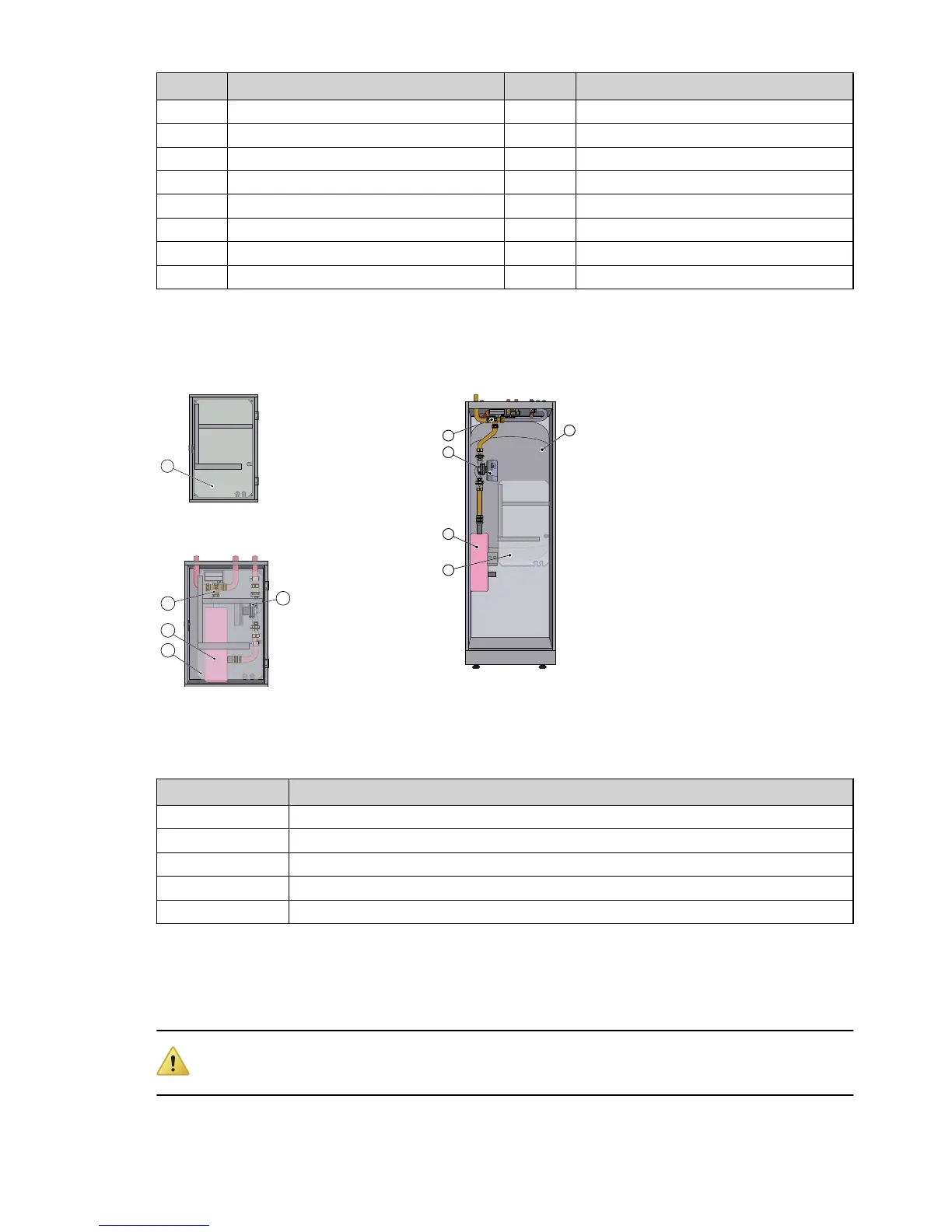
3.2.2 Indoor unit
DHP-AQ Midi
Position Description
1 Control module (transparent in image)
2 Immersion heater
3 Reversing valve
4 Circulation pump
5 Water heater
3.3 Measurement points
Caution! When reading the resistance of the sensors, the sensor leads must first be disconnected from the
control equipment.
Service instructions VMGFJ102 – 11