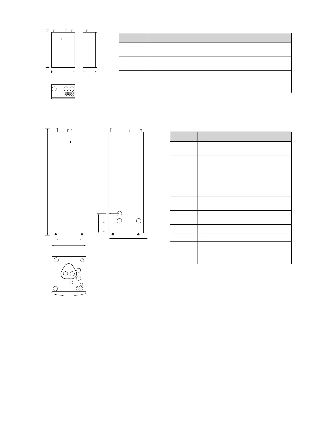
Position Description
1 Supply line for heating system,
28 mm Cu
2 Supply line to water heater,
28 mm Cu
3 Supply line from heat pump,
28 mm Cu
4 Lead-in for supply, sensor and communication cables
Control unitDHP-AQ Maxi
1845 ±10
596
455
690
1
2
3
4
5
125
210
330
6
7
8
9
10
Position Description
1 Supply line heating system,
28 mm Cu
2 Return line heating system,
28 mm Cu
3 Connection for bleed valve,
22 mm Cu
4 Hot water line,
22 mm Cu
5 Cold water line,
22 mm Cu
6 Lead-in for supply, sensor and communica-
tion cables
7 Supply or return line heat pump
8 Supply or return line heat pump
9 Extra knock-out
10 Safety valve for temperature and pressure
(only applies to certain models)
Position 7 and 8 can be connected to either the left or right-
hand side or bottom of the control unit.
14 – Installation instructions VMGFD102

 Loading...