5.2.2.4 Example system solution 2
System solution for DHP-AL, DHP-AL Opti.
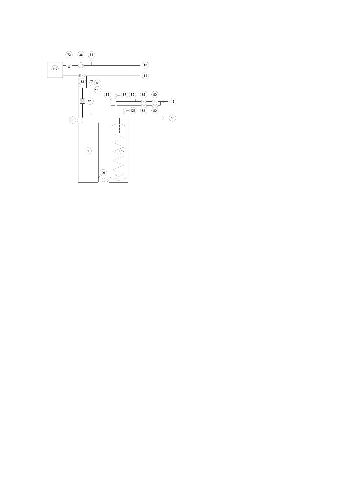
Figure 23. Example system solution 2
Symbol explanation
1 Heat pump
10 Supply line
11 Return line
12 Cold water
13 Hot-water
17 Water heater (DHP-AL)
36 Circulation pump
51 Supply line sensor, moved out from heat pump
72 Additional shunt
80 Shut-off valve
83 Non-return valve
85 Venting valve
86 Safety valve expansion heating system
87 Safety valve cold water 9 bar
89 Vacuum valve
91 Strainer
96 Flexible hose
113 Expansion heating system
117 External auxiliary heater
126 Safety valve for temperature and pressure (only
applies to certain models)
5.2.3 System solution 3
In system solution 3, the heat pump can produce both heat and hot water and an external auxiliary heater (oil
boiler, district heating or similar) supports heat and hot water production and can support antilegionella. The
exchange valve for heating/hot water is located after the external auxiliary heater, which prevents the production
of heating and hot water at the same time.
The integrated auxiliary heater can be used for heating and hot water production as well as for antilegionella.
The parameter "TOPH.AUX” is used to determine if the external or internal auxiliary heater produces antilegionella.
The values of the integrals, A2 and A3 are used to select if the external auxiliary heater is to step in before or after
the integrated electrical auxiliary heater.
The heat pump control computer also controls an additional shunt located after the external addition.
For system solution 3, select in menu SERVICE\AUX. HEATER\EXTERNAL ADDITION:
EXT.AUX.HEATER = ON
REV.V. HOT WATER = EXT
Installation instructions VMBMA1002 – 29
 Loading...


