8.4 Sub-menu TEMPERATURE
The history of different temperature measurements can be viewed by pressing the right arrow key. The graph
shows the last 60 measurement points for the set time interval (SERVICE -> INSTALLATION -> LOG TIME). In the
event of an alarm, history stops being logged until the alarm is reset by changing the operating mode to OFF.
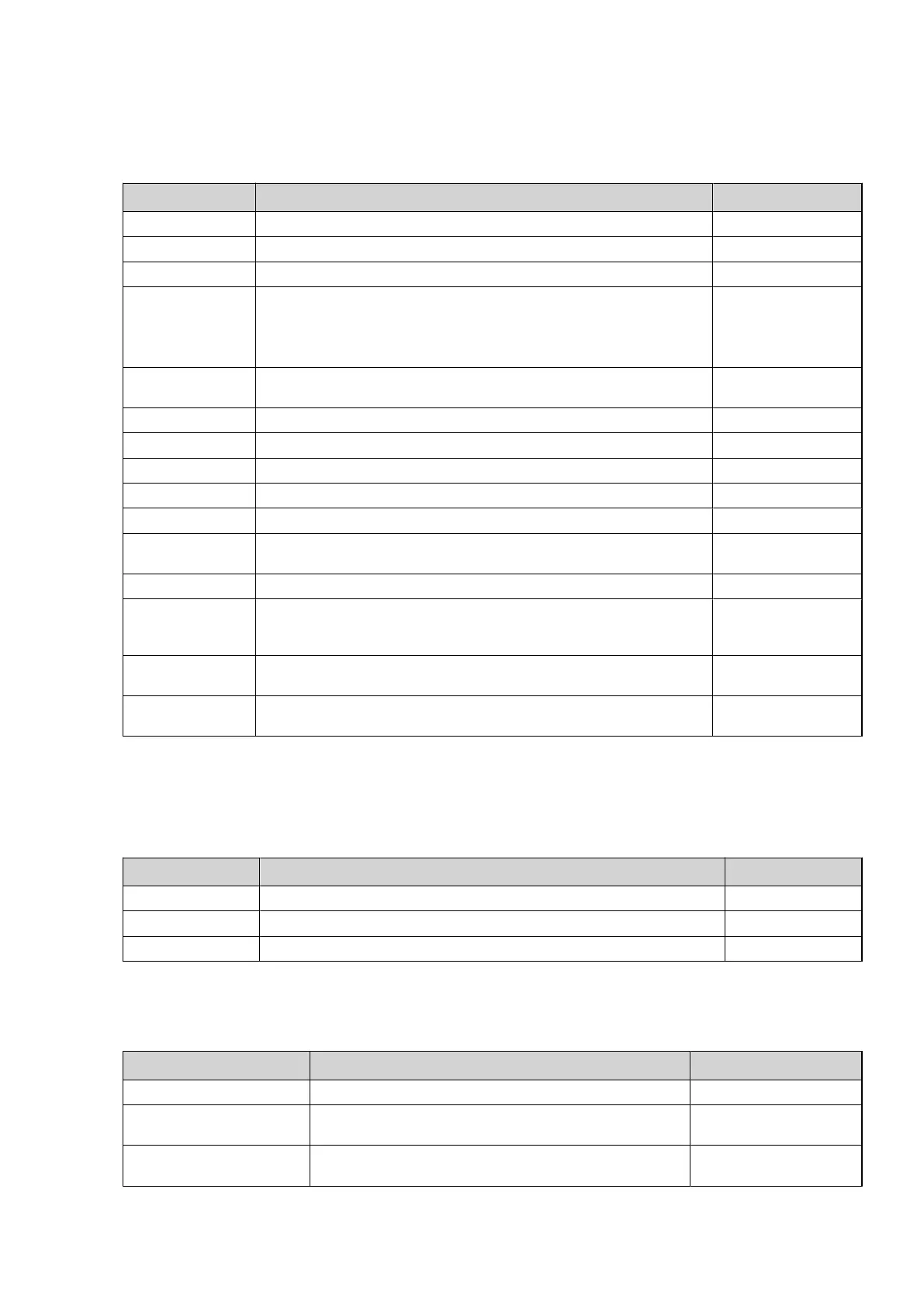
Table 12. Used to indicate the prevailing temperatures, history and set/calculated values.
Menu selection Meaning Factory setting
OUTDOOR Shows the actual outdoor temperature. -
ROOM Shows the actual set temperature. -
SYSTEM SUPPLY Displays system supply temperature at the buffer tank system. -
SUPPLY LINE Shows the actual supply temperature. The calculated supply temperature to
the heating system group is within brackets.
During hot water production in operating mode AUX. HEATER the value for
HOT WATER STOP + 10° is shown within brackets.
-
RETURN LINE Shows the actual return temperature. The stop temperature, MAX RETURN is
within brackets.
-
BUFFER TANK Indicates the buffer tank temperature, if activated. -
HOT WATER Indicates actual hot water temperature, if activated. -
INTEGRAL Shows the actual calculated value for integral. -
BRINE IN Shows the actual temperature for brine in. -
BRINE OUT Shows the actual temperature for brine out. -
POOL Only appears if POOL is selected. Shows the actual pool temperature.
The set pool temperature is shown in brackets.
-
COOLING Indicates temperature.
SHUNT GROUP Only appears if SHUNT GROUP is selected. Shows the actual supply tempera-
ture. The calculated supply temperature to the shunt group is within brack-
ets.
-
2ND HEAT CIR. Shows the temperature of the second heating circuit if installed by the buffer
tank system.
CURRENT Only appears if CURRENT LIMITER is selected. Shows the actual current con-
sumption. The set value for MAX CURRENT is shown in brackets.
-
8.5 Sub-menu OPERAT.TIME
Table 13. Used to show the operating time for each component. Time given in hours.
Menu selection Meaning Factory setting
HEAT PUMP Compressor operating time for both heating and hot water production. -
AUX. HEATER Operating time of auxiliary heater. -
HOT WATER Operating time for hot water with compressor. -
8.6 Sub-menu DEFROST
Table 14. Used to obtain information about defrosting settings and to make defrosting settings.
Menu selection Meaning Factory setting
DEFROSTS Total number of defrosts carried out. -
BETW. 2 DEFR The operating time of the compressor in minutes between the
two last defrosts.
-
TIME LAST DEFR The operating time of the compressor in minutes since last
defrost.
-
Installation instructions VMBMA1002 – 49
 Loading...


