DHP-A, DHP-A Opti, DHP-AL, DHP-AL Opti
6 kW 8 kW 10 kW 12 kW
400V, 3-N A
10
1
/16
2
/20
3
/20
4
/
25
5
/25
6
/30
7
16
1
/16
2
/20
3
/20
4
/
25
5
/25
6
/30
7
16
1
/16
2
/20
3
/20
4
/
25
5
/30
6
/35
7
16
1
/20
2
/25
3
/25
4
/
25
5
/30
6
/35
7
230V, 1-N A
25
1
/32
2
/40
3
25
1
/32
2
/40
3
32
1
/40
2
/50
3
32
1
/40
2
/50
3
1. Heat pump with 3 kW immersion heater (1-N 1.5 kW).
2. Heat pump with 6 kW immersion heater (1-N 3 kW).
3. Heat pump with 9 kW immersion heater (1-N 4.5 kW).
4. Heat pump with 12 kW immersion heater and shut off compressor
5. Heat pump with 15 kW immersion heater and shut off compressor
6. Heat pump with 12 kW immersion heater
7. Heat pump with 15 kW immersion heater
8. Fuse phase L1 (size 4 has 1-phase compressor)
6.3 Connecting external supply voltage
DANGER! Electrical voltage! The power cable may only be connected to the terminal block intended for
this purpose. No other terminal blocks may be used!
1. Route the power cable through the opening in the top panel of the heat pump to the terminal blocks.
2. Connect the power cable as follows.
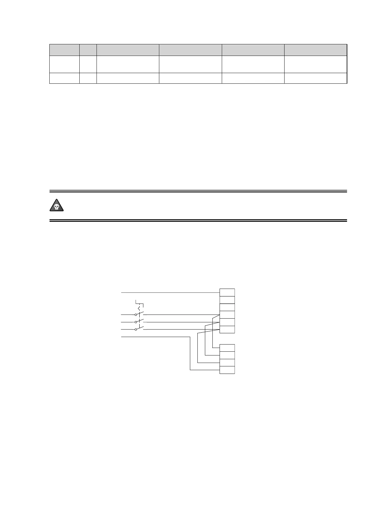
6.3.1 Connection 400 V, 3-N
Circuit-breaker Terminal block heat pump
Incoming cable
2 1
4 3
6 5
N3 3L1 PE5 1L1 1L2 1L3 2L1 2L2 2L3 PE1
Figure 39. Connection 400V 3N
Installation instructions VMBMA1002 – 39
 Loading...