Do you have a question about the Danfoss DLX 2.9 UL and is the answer not in the manual?
Details approved standards and directives for DLX UL inverters.
Provides general information and variations available for the DLX UL series.
Lists the DLX UL solar inverter series covered by this guide.
Describes available options such as grounding systems and DC fuses.
Highlights the main features and benefits of the DLX UL inverter.
Explains the warning symbols used in the guide and on the inverter.
Details the product label and its information.
Describes the information found on the inverter's product label.
Identifies important information about different terminals on the PCB.
Instructions for safely unpacking and inspecting the inverter.
Procedures for reporting shipping damage to the inverter.
Guidelines for safely lifting and carrying the inverter to prevent injury.
Step-by-step instructions for unpacking the inverter.
Lists the components included in the inverter's scope of delivery.
Describes the design and protection features of the inverter housing.
Provides the physical dimensions of the inverter.
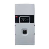
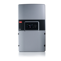
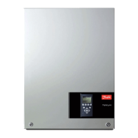
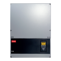
Details the front surface components of the inverter.
Instructions for removing the inverter's lower cover.
Outlines general safety preparations and qualifications required for handling the inverter.
Instructions for contacting utility companies and initial connection safety.
Safety guidelines for operating the DLX UL inverter.
Safety precautions before performing maintenance on the inverter.
Precautions for selecting and preparing a suitable installation site.
Guidelines for choosing an optimal mounting location for the inverter.
Environmental considerations for inverter installation and operation.
Lists essential safety equipment for inverter installation and operation.
Explains the importance and types of disconnection devices.
Details overcurrent protection devices like fuses and circuit breakers.
Information on Ground Fault Detection and Interruption (GFDI).
Guidelines for selecting and using DC fuses for the inverter.
Details on AC overcurrent protection requirements.
Information on surge protection devices and lightning protection.
Procedures for physically mounting the inverter.
Instructions for mounting the inverter using a wall bracket.
Steps to attach the inverter to the mounting bracket.
Essential checks before proceeding with electrical connections.
Guidelines for correct electrical connections for safe operation.
Criteria for selecting appropriate conductors based on ampacity and voltage drop.
Identifies and describes the various terminals in the connection area.
Information on using knock-outs and conduit fittings for the Stringbox.
Procedures and requirements for proper system grounding.
Wiring instructions for connecting PV modules to the inverter.
Details the DC terminal blocks for PV connections.
Guidance on configuring PV arrays and string connections.
Information on the DC disconnect switch and its operation.
Explains the setup for positive grounded PV strings.
Step-by-step procedures for DC conductor connections.
Hazards and procedures for reversed DC connections.
Details jumper settings for system grounding configurations.
Instructions for connecting the inverter to the AC grid.
Procedures for AC conductor connections based on supply voltage.
Information on connecting the inverter via Ethernet, CAN, and RS-485.
Steps for establishing network connections.
Explains jumper settings for network termination resistance.
Final checks to perform before initiating the inverter's startup.
Procedures for the first-time startup and initial configuration.
Guidance on configuring inverter settings during initial startup.
Describes initial setup for a single inverter.
Initial setup procedures for multiple inverters in a network.
Configuring multiple inverters using the CAN bus.
Configuring multiple inverters using the RS-485 bus.
Overview of the inverter's user interface components.
Details the inverter's LCD screen and menu navigation.
Explains the meaning of the status LEDs on the inverter.
Describes the functions of the inverter's control keys.
The initial installation screen displayed on startup.
The first step in the installation process.
How to select the preferred language for the interface.
Setting the correct date for the inverter.
Setting the correct time for the inverter.
Configuring the Bus ID for RS-485 communication.
Configuring the inverter to act as the master unit in a system.
Selecting the appropriate grid configuration for the installation.
Setting the display backlight timeout duration.
Entering the customer or owner name for identification.
Setting the site name for the installation.
Assigning a name to identify a specific inverter.
Adding a custom message for inverter identification.
Setting or changing the owner password.
Explains the different access levels and password requirements.
Describes the default display screen and its content.
Displays operational data for a single inverter.
Displays operational data for a PV plant with multiple inverters.
Details the upper section of the display showing status and mode.
Details the lower section of the display showing date, time, and menu access.
Displays operating modes and status of the inverter and PV plant.
Shows detailed information about active alarms and status signs.
Displays operating mode, status, and parameters of the inverter.
Displays status and parameters for the entire PV plant.
Accesses settings and data for the inverter, grid, and PV plant.
Configures general inverter parameters like language, date, and time.
Configures network settings for communication.
Displays read-only data for the specific inverter model.
Information about the PV plant, changeable by the owner.
Configures grid parameters based on the selected country.
Adjustable voltage trip limits for different grid configurations.
Adjustable frequency trip limits for grid connection.
Procedures for modifying grid code settings.
Options to delete stored data in the inverter logger.
Commands to delete inverter-specific logged events.
Commands to delete plant-specific logged events.
Configuration of email notifications for alarms and status.
Settings for email server, recipients, and sender address.
Defines notification types and time intervals for inverter emails.
Settings for uploading data to a web portal.
Displays logged events, warnings, and alarms in chronological order.
Displays daily, monthly, and yearly energy harvest and earnings.
Summary of inverter statistics for today, month, and year.
Summary of PV plant statistics for today, month, and year.
How to connect the inverter to a computer for monitoring.
Connecting the inverter directly to a computer via Ethernet.
Configuring IP addresses for computer and inverter communication.
Connecting the inverter to a computer via a LAN or WAN network.
Setting up dynamic IP addressing for network connection.
Setting up static IP addressing for network connection.
Steps to make the inverter accessible from the internet.
Accessing detailed information via the inverter's onboard web server.
The standard home screen of the web server interface.
Graphical overview of energy production from the web interface.
Accessing and modifying various settings via the web interface.
Viewing logged events and alarms from the web interface.
Displays plant and inverter status, warnings, and alarms.
A checklist to diagnose and resolve common inverter failures.
Explains messages displayed during inverter failures and their meanings.
Procedures for safely switching off and discharging the inverter.
Importance and general procedures for regular system maintenance.
Maintenance recommendations for PV modules.
Instructions for checking and maintaining cables.
Checking the tightness and condition of electrical connections.
Procedures for dealing with blown fuses or tripped circuit breakers.
Specific instructions for replacing DC fuses.
Recommendations for operating the DC disconnect switch.
Periodic checks for humidity and dust inside the inverter.
Maintaining clean heatsinks and ventilation for cooling.
Information on fan replacement and its importance.
Regular inspection and replacement of varistors.
Procedures for replacing DC side varistors.
Procedures for checking and replacing AC side varistors.
Procedures for replacing the inverter unit.
Steps for removing the inverter from its mounting bracket.
Procedures for installing a new inverter.
Guidelines for returning or disposing of the inverter.
Procedures for returning the inverter for service or replacement.
Information on proper disposal of the inverter.
Details on warranty coverage and service procedures.
Conditions under which the warranty may be voided.
Lists causes of damage for which Danfoss is not responsible.
Provides detailed technical specifications for the DLX UL inverters.
Lists adjustable trip levels for voltage and frequency settings.