3.1.2 Connections and dimensions
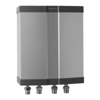
For Danfoss DWH 200, see figure 1.
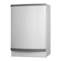
For Danfoss DWH 300 / DWH H 200, see figure 2.
Symbol explanation
1. Return pipe to heat pump Ø 22 mm
2. Hot water Ø 22 mm
3. Cold water Ø 22 mm
4. Inlet from heat source Ø 22 mm
5. Lead-ins
6. Venting,
Water heaters DWH 200 DWH H 200 DWH 300
Volume V 171,9 171,9 280,0
Calc. pressure Sec/prim, Mpa 1.0/0.3 1.0/0.3 1.0/0.3
Test pressure Sec/prim, Mpa 1.43/0.43 1.43/0.43 1.43/0.43
Weight empty, kg 95 110 115
Weight full, kg 285 300 410
Height, H*, mm 1538 1845 1845
Standing loss S 59,3 59,3 91,7
Energy efficiency class C C C
*) The height applies with the feet set at the lowest level ForDWH Pro the height applies without the design top installed.
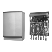
3.1.3 Installation
1. Detach the front cover by twisting the catch 90° anticlockwise.
2. At the same time hold the front cover with one hand.
3. Lift the front cover upwards to remove it from the hot water heater.
3.1.4 Positioning
•Position Danfoss DWH on a floor that can bear their weight.
• The room must be equipped with a floor drain.
• Danfoss DWH are intended for upright installation.
• For minimum ceiling height for elevating the heater, see figure 6.
• The hot water tank is positioned and then the pipes are connected. If the tank is to be installed together with a heat pump it must be
positioned beside the heat pump and connected with a flexible connection.
3.1.5 Piping installation
For general connection diagram for DHP-L Opti and DWH, see figure 3.
For general connection diagram for DHP-L Opti Pro/DHP-L Opti Pro+ and DWH Pro/Pro+ (incl. temperature/pressure valve), see UK
Appendix.
For general connection diagram for DHP-H Opti and DWH, see figure 5.
Installation Guide DWH
VMBNB82J
Danfoss Heating Solutions
12
 Loading...