EKC 315A Manual RS8CS302 © Danfoss 07-2005 9
Factory setting
If you need to return to the factory-set values, it can be done in this way:
- Cut out the supply voltage to the controller
- Keep both buttons depressed at the same time as you reconnect the supply voltage
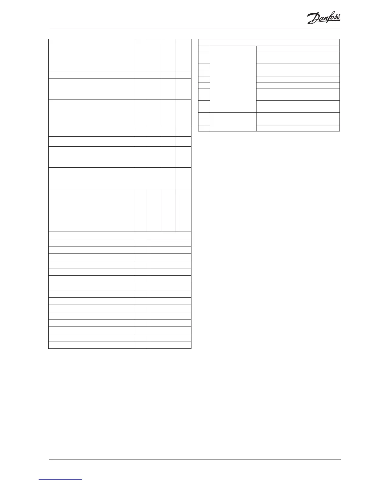
The controller can give the following messages:
E1
Error message
Fault in controller
E11 Valve’s actuator temperature outside its range
E15 Cut-out S2 sensor
E16 Shortcircuited S2 sensor
E17 Cut-out S3 sensor
E18 Shortcircuited S3 sensor
E19
The input signal on terminals 18-19 is outside
the range.
E20
The input signal on terminals 14-15 is outside
the range (P0 signal)
A1
Alarm message
High-temperature alarm
A2 Low-temperature alarm
A11 No refrigerant has been selected
Define input signal on the analoge input AIA:
0: no signal,
1: Temperature setpoint. 0-20 mA
2: Temperature setpoint. 4-20 mA
3: Displacement of superheat reference. 0-20 mA
4: Displacement of superheat reference. 4-20 mA
o10 0 4 0
Set supply voltage frequency
o12 50 Hz 60 Hz 0
Select display for ”normal picture”
1: Superheat
2: Valve’s opening degree
3: Air temperature
o17 1 3 1
Manual control of outputs:
OFF: no manual control
1: Relay for solenoid valve: select ON
2: AKV/A output: select ON
3: Alarm relay activated (cut out)
o18 off 3 Off
Working range for pressure transmitter – min.
value
o20 -1 bar 60 bar -1.0
Working range for pressure transmitter – max.
value
o21 -1 bar 60 bar 12
(Setting for the function o09)
Set the temperature value or opening degree
where the output signal must be minimum (0 or
4 mA)
o27 -70°C 160°C -35
(Setting for the function o09)
Set the temperature value or opening degree
where the output signal must be maximum (20
mA)
o28 -70°C 160°C 15
Refrigerant setting
1=R12. 2=R22. 3=R134a. 4=R502. 5=R717.
6=R13. 7=R13b1. 8=R23. 9=R500. 10=R503.
11=R114. 12=R142b. 13=User defined. 14=R32.
15=R227. 16=R401A. 17=R507. 18=R402A.
19=R404A. 20=R407C. 21=R407A. 22=R407B.
23=R410A. 24=R170. 25=R290. 26=R600.
27=R600a. 28=R744. 29=R1270.
o30 0 29 0
Service
TQ valve's actuator temperature
u04 °C
Reference of the valve's actuator temperature
u05 °C
Analog input AIA (18-19) u06 mA
Analog output AO (2-5)
u08 mA
Read status of input DI
u10 on/off
Thermostat cut-in time
u18 min.
Temperature at S2 sensor
u20 °C
Superheat
u21 K
Superheat reference
u22 K
Read AKV valve’s opening degree
u24 %
Read evaporating pressure
u25 bar
Read evaporating temperature
u26 °C
Temperature at S3 sensor
u27 °C
Temperature reference
u28 °C
Read signal at pressure transmitter input
u29 mA
*) This setting will only be possible if a data communication module has been
installed in the controller.
 Loading...