2 Instructions RI8NG552 © Danfoss 10/2011 EKC 326A
0 V = ventil lukket, Valve closed, Ventil geschlossen, Vanne fermée
10 V = ventil åben Valve open Ventil offen Vanne ouverte
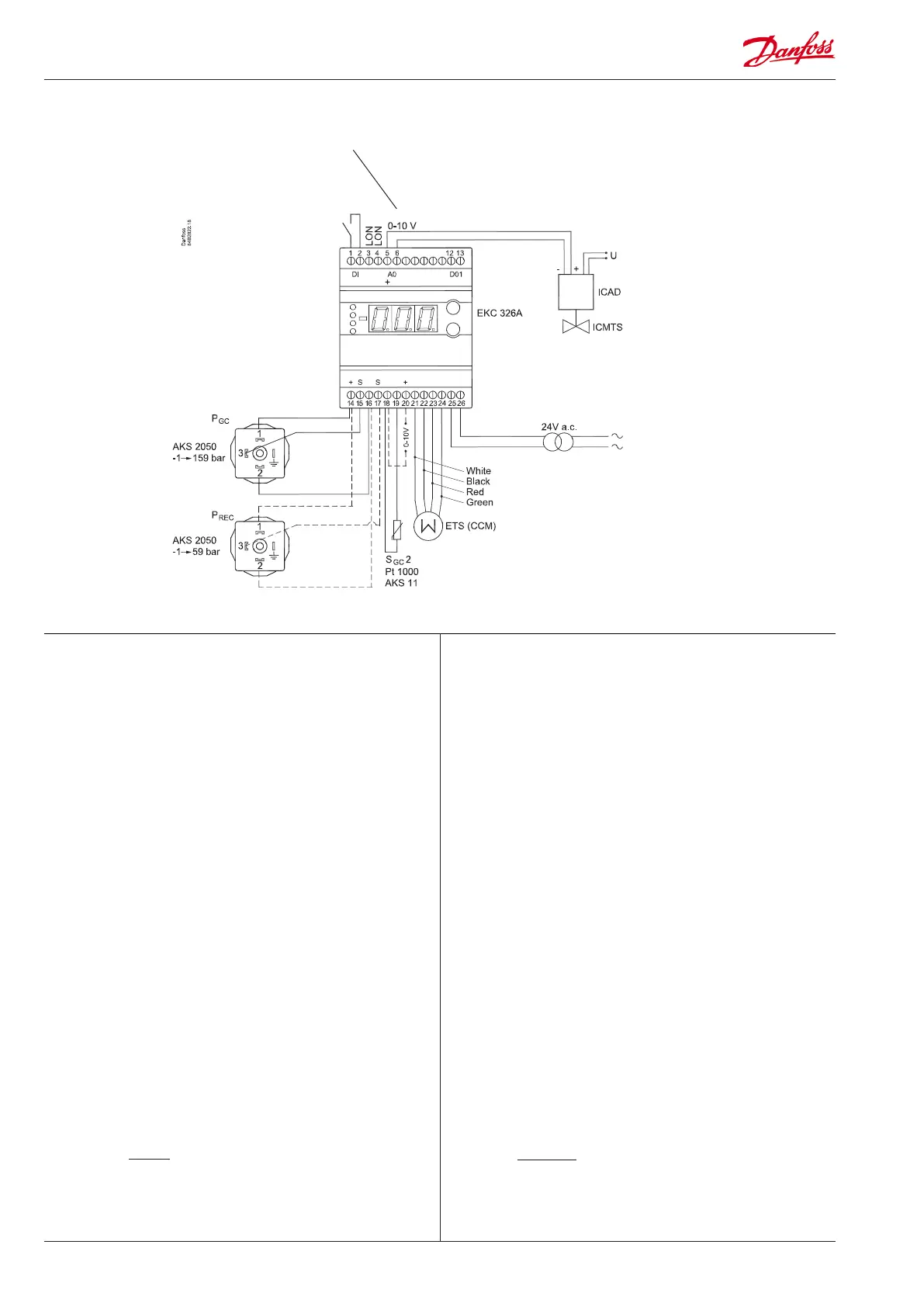
Necessary connections
Terminals:
25-26 Supply voltage 24 V a.c.
18-19 Pt 1000 sensor at gas cooler outlet (S
GC
2
)
14,15,16 Pressure transmitter AKS 2050, -1 to 159 bar
To register the correct pressure it must be mounted as
close as possible to the gas cooler.
5-6 Voltage output to control the ICMTS valve.
Application dependent connections
Terminals:
1-2 DI-input to either:
• External main switch (see o02 and r12)
OR
Contact function for increasing capacity (optimised COP
operation stopped). (see o02)
Open connection = optimised COP operation
Closed connection = extra capacity.
12-13 Alarm relay
There is connection between 12 and 13 in alarm situa tions
14,16,17 Optional. A pressure transmitter can be connected so
that the pressure in the receiver can be monitored. The
pressure transmitter must be an AKS 2050, -1 to 59 bar.
21-24 If receiver pressure is to be controlled, a CCM or ETS valve
should be connected.
18-20 Heat recovery. A voltage signal between 2 and 10 V will
increase the gas pressure reference.
3-4 Data communication
Mount only, if a data communication module has been
mounted.
It is important that the installation of the data communi-
cation cable be done correctly. Cf. separate literature No.
RC8AC...
Important
PGC and SGC2 must be mounted near the gas cooler outlet to produce
a correct signal.
High pressure valve
Vhp
Gas bypass valve
Vgbp
8 VA
DANSK
ENGLISH
Tilslutninger
Connections
Nødvendige tilslutninger
Klemme:
25-26 Forsyningsspænding 24 V a.c.
18-19 Pt 1000 føler ved gaskølerafgang (S
GC
2
)
14,15,16 Tryktransmitter type AKS 2050, -1 til 159 bar
For at registrere det korrekte tryk skal den monteres så
tæt ved gaskøleren som muligt.
5-6 Spændingsudgang til styring af ICMTS ventil.
Applicationbestemte tilslutninger
Klemme:
1-2 DI-indgang til enten:
• Ekstern hovedafbryder (se o02 og r12)
ELLER
Kontaktfunktion til hævning af kapaciteten (optimeret
COP-drift stoppes) (se o02).
Åben forbindelse = optimeret COP-drift
Sluttet forbindelse = extra kapacitet.
12-13 Alarmrelæet
Der er forbindelse imellem 12 og 13 i alarmsituationer.
14,16,17 Optional. Der kan tilsluttes en tryktransmitter, så trykket
i receiveren kan følges. Tryktransmitteren skal være en
AKS 2050, -1 til 59 bar.
21-24 Hvis trykket i receiveren skal reguleres, skal der tilsluttes
en ventil type CCM eller ETS.
18-20 Varmegenvinding. Et spændingssignal på 2-10 V vil hæve
gastryksreferencen.
3-4 Datakommunikation
Monteres kun, hvis der også er monteret et datakommuni-
kationsmodul.
Det er vigtigt, at installationen af datakommunikations-
kablet udføres korrekt.
Se separat litteratur nr. RC8AC...
Vigtigt
PGC og SGC2 skal monteres tæt ved gaskølerens afgang for at give
korrekt signal.
Cable connection
060G1034
14 = black
15 = brown
16 = blue
AKS 11: Max. 100°C
AKS 21: Max. 180°C
L > 5 m => AKA 211. Se manual
L > 5 m => AKA 211. See manual
L > 5 m => AKA 211. Siehe Manual
L > 5 m => AKA 211. Voir manual
<-------max. 5 m ---------------->

 Loading...