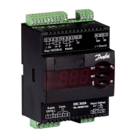
EKC 326A Instructions RI8NG552 © Danfoss 10/2011 7
*) This setting will only be possible if a data communication module has been installed in the
controller.
**) The display on the controller can show 3 digits only, but the setting value has 4 digits. Only the
3 most important will be shown. It means fx. 250 will give a setting of 2500.
Miscellaneous
Digital input signal - DI
0: The input is not used
1: External main switch
2: additional cooling capacity
o02 0 2 0
Controller’s address o03* 0 240 -
ON/OFF switch (service-pin message) o04* - - -
Set supply voltage frequency o12
50Hz
(0)
60 Hz
(1)
0
Pressure transmitter range Pgc - min. o20 -1 bar 5 bar -1
Pressure transmitter range Pgc - max. o21 6 bar 199 bar 159
Pressure transmitter range Prec - min. o47 -1 bar 5 bar -1
Pressure transmitter range Prec - max. o48 6 bar 199 bar 59
Service
Signal on AI the input u07 V
Read status of input DI u10 on/off
Read ETS/CCM valves opening degree u24 %
Calculated reference for regulation (desired pres-
sure in the gas cooler)
U03 bar
The output signal to the ICMTS valve converted
into opening degree
U04 %
The temperature in the gas cooler. Measured
using temperature sensor Sgc.
U05 °C
The pressure in the gas cooler. Measured using
pressure transmitter Pgc.
U06 bar
The pressure in the receiver. Measured using
pressure transmitter Prec, but only if it is
mounted.
U07 bar

 Loading...