EasyManua.ls Logo

Danfoss KP 15 - User Manual

Danfoss KP 15
4 pages
To Next Page IconTo Next Page
Loading...
Pressure Controls
KP 15, KP 17W, KP 17B, KP 25
©Danfoss A/S RI5AK222 - 520H0146
060R9747
060R9747
Instructions
Types
The controls can be used with CFC, HFC, HCFC refrigerants.
CAUTION: Do not install these controls on
ammonia systems
KP 15 man. (LP) / man. (HP) reset KP 15, KP 17B auto. (LP) / man. (HP) reset KP 15, KP 17W, KP 25 auto. (LP) / auto (HP) reset
Ambient temperatures Test pressure (p
TEST
)
p
test
max.
505 psig
(35 bar p
e
)
p
test
max.
285 psig
(20 bar p
e
)
t
1
min. KP 15, KP 25: –40°F (–40°C)
KP 17W, KP 17B: –13°F (–25°C)
t
1
max. 150°F (65°C)
CAUTION: Do not mount the control in a position where dirt, sediment,
or oil will aff ect the operation of the control.
Enclosure
CAUTION: The mounting panel must be plane to avoid damage of control.

Other manuals for Danfoss KP 15

Question and Answer IconNeed help?

Do you have a question about the Danfoss KP 15 and is the answer not in the manual?

Danfoss KP 15 Specifications

General IconGeneral
BrandDanfoss
ModelKP 15
CategorySwitch
LanguageEnglish

Summary

Pressure Controls KP 15 KP 17 W KP 17 B KP 25

Control Types and Compatibility

Explains compatibility with CFC, HFC, HCFC refrigerants and warns against ammonia systems.

Ambient Temperature Specifications

Details minimum and maximum operating ambient temperature limits.

Test Pressure Ratings

Provides maximum test pressure values for LP and HP sides.

Enclosure Features and Mounting

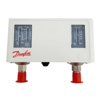
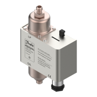
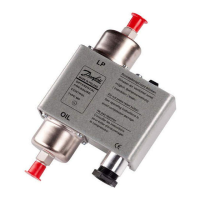
Covers enclosure details, mounting panel requirements, and IP rating.

Electrical Connections and Wiring

Wiring Safety Precautions

Emphasizes disconnecting power before wiring to prevent shock or damage.

SPDT Controls Wiring

Wiring diagrams and instructions for SPDT controls with LP signal.

LP and HP Signal Controls Wiring

Wiring diagrams and instructions for controls with LP and HP signals.

Contact Load Ratings

Lists electrical load ratings for control contacts at various voltages.

Signal Functionality

Illustrates how LP and LP+HP signals operate based on pressure changes.

Manual Tripping and Reset Operations

Manual Tripping Procedure

Instructions for manually tripping the control contacts using fingers or screws.

Convertible Reset Options

Explains how to configure the control for different manual/automatic reset modes.

Resetting After Safety Cut-out

Guidance on how to reset the control after a safety cut-out condition occurs.

Adjustment Spindle Locations

Identifies the location of adjustment spindles for LP and HP settings.

Setting Pressure Control Parameters

Low Pressure (LP) Side Setting

Guides on adjusting the range and differential for the LP side.

High Pressure (HP) Side Setting

Guides on adjusting the range and differential for the HP side.

Differential Setting Explained

Explains how CUT-IN, CUT-OUT, and DIFFERENTIAL values relate.

Adjustment Spindle Operation

Details how to adjust the LP and HP range spindles and differential.

Related product manuals