EasyManua.ls Logo

Danfoss KP 1 User Manual

Danfoss KP 1
4 pages
To Next Page IconTo Next Page
Page #1 background imageLoading...
Page #1 background image
INSTRUCTIONS
KP 1, KP 2,
KP 5, KP 7W, KP 7B
060R9746
RI.05.1A.22 ® RI.5A.J1.22 01-1999
Types
The controls can be used with CFC, HFC
and HCFC refrigerants.
CAUTION: Do not install these controls on
ammonia systems.
CAUTION: Do not mount the control in a position where dirt,
sediment, or oil will affect the operation of the control.
Mounting requirements Ambient temperatures
Auto reset: KP 1, KP 2, KP 5, KP 7W Manual reset: KP 1, KP 5, KP 7B
CAUTION: The mounting panel must be plane to avoid damage of control.
Enclosure
Test pressure (p
TEST
) Connections
060R9746
© Danfoss A/S
t
1
min. KP 1, 2, 5: –40°F (–40°C)
KP 7: –13°F (–25°C)
t
1
max. 150°F (65°C)
p
test
max.:
KP 1, 2: 285 psig (20 bar p
e
)
KP 5, 7: 505 psig (35 bar p
e
)

Other manuals for Danfoss KP 1

Question and Answer IconNeed help?

Do you have a question about the Danfoss KP 1 and is the answer not in the manual?

Danfoss KP 1 Specifications

General IconGeneral
TypePressure switch
Pressure range-0.2 to 7.5 bar
Pressure connection standardG
Contact functionSPDT
Operating temperature-40 to 65 °C
Pressure connection size1/4 inch
Enclosure ratingIP30

Summary

Types of Controls

Refrigerant Compatibility

Controls are compatible with CFC, HFC, and HCFC refrigerants.

Mounting and Installation

Mounting Requirements

Specifies orientation and environmental considerations for control mounting.

Test Pressure (PTEST)

Defines maximum test pressures for different control models.

Enclosure Details

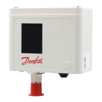
Details on enclosure types like drip-proof IP33 and thread sizes.

Ambient Temperature Limits

Specifies minimum and maximum ambient temperature ranges for control operation.

Connection Types

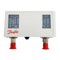
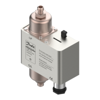
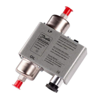
Describes connection types and sizes for the controls.

Wiring and Electrical Connections

Wiring Precautions

Safety and regulatory guidelines for electrical wiring.

Terminal Block and Load Options

Diagrams and explanations for SPDT terminal block and load options A/B.

Contact Load Ratings

Table listing electrical load ratings for different voltage types.

Electrical Contacts/Wiring Test

Procedure for testing control contacts and main lever operation.

Adjustment and Setting Procedures

Setting High/Low Set Points

Instructions for adjusting range and differential spindles for set points.

Differential Adjustment

Guidance on adjusting the differential (difference between cut-in and cut-out).

Manual Reset Operation

Instructions on how to perform manual reset after a safety cutout.

Adjustment Spindle Location

Location of adjustment spindles for range and differential on controls.

Related product manuals