EasyManua.ls Logo

Danfoss KP 1 User Manual

Danfoss KP 1
4 pages
To Next Page IconTo Next Page
To Previous Page IconTo Previous Page
Page #3 background image
Setting
(se also “Wiring”)
KP 1 (auto reset), KP 2, KP 5, KP 7W and KP 7B KP 1 (manual reset ONLY)
1. Adjust range spindle to desired 1. Adjust range spindle to desired
HIGH SET POINT (HSP) LOW SET POINT (LSP)
2. Adjust differential spindle to 2. DIFFERENTIAL is fixed.
desired DIFFERENTIAL (DIFF.) Value printed on scale plate
Note:
KP 5 (manual reset) and KP 7B have fixed diff.
Value printed on scale plate.
HIGH SET POINT minus DIFFERENTIAL equals LOW SET POINT LOW SET POINT plus DIFFERENTIAL equals HIGH SET POINT
Example: Example:
HSP DIFF. = LSP LSP + DIFF. = HSP
30 psig 20 psi = 10 psig 12 psig + 10 psi = 22 psig
(2.1 bar) (1.4 bar) (0.7 bar) (0.8 bar) (0.7 bar) (1.5 bar)
If terminals 1-4 are used: CUT-IN = HSP
CUT-OUT = LSP
If terminals 1-2 are used: CUT-IN = LSP
CUT-OUT = HSP
RI.5A.J1.22 © Danfoss A/S
10 psi (0.7 bar) /
rev. KP 1
7 psi (0.5 bar) /
rev. KP 2
33 psi (2.3 bar) /
rev. KP 5, 7W, 7B
3 psi (0.2 bar) / rev. KP 1
1.5 psi (0.1 bar) / rev. KP 2
4 psi (0.3 bar) / rev. KP 5
7 psi (0.5 bar) / rev. KP 7W
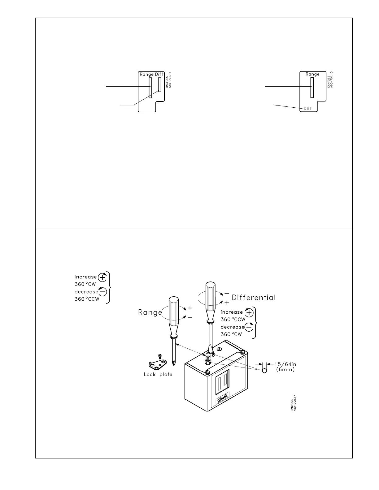
Adjustment
See instruction printed on top of control
Note:
Remove lock plate before adjustment.
Replace lock plate after adjustment (if desired).

Other manuals for Danfoss KP 1

Question and Answer IconNeed help?

Do you have a question about the Danfoss KP 1 and is the answer not in the manual?

Danfoss KP 1 Specifications

General IconGeneral
TypePressure switch
Pressure range-0.2 to 7.5 bar
Pressure connection standardG
Contact functionSPDT
Operating temperature-40 to 65 °C
Pressure connection size1/4 inch
Enclosure ratingIP30

Summary

Types of Controls

Refrigerant Compatibility

Controls are compatible with CFC, HFC, and HCFC refrigerants.

Mounting and Installation

Mounting Requirements

Specifies orientation and environmental considerations for control mounting.

Test Pressure (PTEST)

Defines maximum test pressures for different control models.

Enclosure Details

Details on enclosure types like drip-proof IP33 and thread sizes.

Ambient Temperature Limits

Specifies minimum and maximum ambient temperature ranges for control operation.

Connection Types

Describes connection types and sizes for the controls.

Wiring and Electrical Connections

Wiring Precautions

Safety and regulatory guidelines for electrical wiring.

Terminal Block and Load Options

Diagrams and explanations for SPDT terminal block and load options A/B.

Contact Load Ratings

Table listing electrical load ratings for different voltage types.

Electrical Contacts/Wiring Test

Procedure for testing control contacts and main lever operation.

Adjustment and Setting Procedures

Setting High/Low Set Points

Instructions for adjusting range and differential spindles for set points.

Differential Adjustment

Guidance on adjusting the differential (difference between cut-in and cut-out).

Manual Reset Operation

Instructions on how to perform manual reset after a safety cutout.

Adjustment Spindle Location

Location of adjustment spindles for range and differential on controls.

Related product manuals