Instructions
© Danfoss | DCS (CC) | 2018.03 | 3
8510196P04H - FRCC.PI.049.A4.02
1 - Introduction
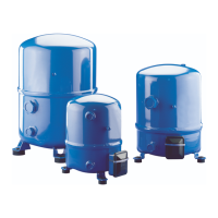
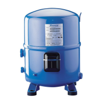
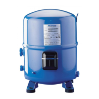
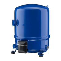
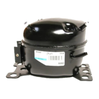
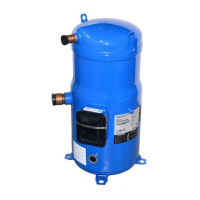
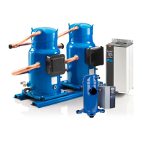
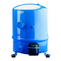
These instructions pertain to the Maneurop® MT,
MTZ,VTZ & NTZ compressors used for refrigera-
tion systems. They provide necessary informa-
tion regarding safety and proper usage of this
product.
2 – Handling and storage
• Handle the compressor with care. Use the
dedicated handles in the packaging. Use the
compressor lifting lug and use appropriate
and safe lifting equipment.
• Store and transport the compressor in an
upright position.
• Store the compressor between -35°C and
50°C.
• Don’t expose the compressor and the packa-
ging to rain or corrosive atmosphere.
3 – Safety measures before assembly
Never use the compressor in a ammable at-
mosphere.
• The compressor ambient temperature may
not exceed 50°C during o-cycle.
• Mount the compressor on a horizontal at
surface with less than 3° slope.
• Verify that the power supply corresponds to
the compressor motor characteristics (see
nameplate).
• When installing MTZ,VTZ or NTZ, use equip-
ment specically reserved for HFC refrigerants
which was never used for CFC refrigerants.
• Use clean and dehydrated refrigeration-grade
copper tubes and silver alloy brazing material.
• Use clean and dehydrated system components.
• The piping connected to the compressor must
be exible in 3 dimensions to dampen vibrations.
4 - Assembly
• Slowly release the nitrogen holding charge
through the schrader port.
• Remove the gaskets when brazing rotolock
connectors.
• Always use new gaskets for assembly.
• Connect the compressor to the system as
soon as possible to avoid oil contamination
from ambient moisture.
• Avoid material entering into the system while
cutting tubes. Never drill holes where burrs
cannot be removed.
• Braze with great care using state-of-the-art tech-
nique and vent piping with nitrogen gas ow.
• Connect the required safety and control de-
vices. When the schrader port is used for this,
remove the internal valve.
5 – Leak detection
Never pressurize the circuit with oxygen or
dry air. This could cause re or explosion.
• Do not use dye for leak detection.
• Perform a leak detection test on the complete
system.
• The low side test pressure must not exceed 25
bar.
• When a leak is discovered, repair the leak and
repeat the leak detection.
6 – Vacuum dehydration
• Never use the compressor to evacuate the
system.
• Connect a vacuum pump to both the LP & HP
sides.
• Evacuate the system to a pressure of 500 µm
Hg (0.67 mbar) absolute.
• Do not use a megohmmeter nor apply power
to the compressor while it is under vacuum as
this may cause internal damage.
7 – Electrical connections
• Switch o and isolate the main power supply.
See overleaf for wiring details.
• The compressor is protected against excess
current and temperature by an internal over-
load protector. Follow local regulations regar-
ding power line protection. The compressor
must be connected to earth.
• All electrical components must be selected as per
local standards and compressor requirements.
8 – Filling the system
• Keep the compressor switched o.
• Fill the refrigerant in liquid phase into the
condenser or liquid receiver. The charge must
be as close as possible to the nominal system
charge to avoid low pressure operation and
excessive superheat.
• Keep the refrigerant charge below 2.5 kg per
compressor cylinder if possible. Above this
limit; protect the compressor against liquid
ood-back with a pump-down cycle or suc-
tion line accumulator.
• Never leave the lling cylinder connected to
the circuit to avoid overlling.
9 – Verification before commissioning
Use safety devices such as safety pressure
switch and mechanical relief valve in compliance
with both generally and locally applicable regu-
lations and safety standards. Ensure that they
are operational and properly set.
Check that the settings of high-pressure swit-
ches and relief valves don’t exceed the maximum
service pressure of any system component.
• A low-pressure switch is recommended to
avoid vacuum operation. Minimum setting
0.1 bar.
• Verify that all electrical connections are pro-
perly fastened and in compliance with local
regulations.
• When a crankcase heater is required, it must be
energized at least 12 hours before initial start-
up and start-up after prolonged shutdown.
10 – Start-up
• All service valves must be in the open position.
• Balance the HP/LP pressure.
• Energize the compressor. It must start
promptly. If it does not, switch it o
immediately. Possible single phase miswiring
can cause burn-out within seconds.
• If the compressor does not start, check wiring
conformity and voltage on terminals.
• If the internal overload protector trips out, it
must cool down to 60°C to reset. Depending
on ambient temperature, this may take up to
several hours.
11 – Check with running compressor
• Check current draw and voltage.
• Check suction superheat to reduce risk of
slugging.
• When a sight glass is provided observe the oil
level at start and during operation to conrm
that the oil level remains visible.
• Respect the operating limits as printed overleaf.
• Check all tubes for abnormal vibration. Move-
ments in excess of 1.5 mm require corrective
measures such as tube brackets.
• When needed, additional refrigerant in the
liquid phase may be added in the low-pressure
side as far as possible from the compressor.
The compressor must be operating during
this process.
• Do not overcharge the system.
• Never release refrigerant to the atmosphere.
• Before leaving the installation site, carry out
a general installation inspection regarding
cleanliness, noise and leak detection.
• Record type and amount of refrigerant charge
as well as operating conditions as a reference
for future inspections.
12 - Maintenance
Internal pressure and surface temperature
are dangerous and may cause permanent inju-
ry.Maintenance operators and installers require
appropriate skills and tools. Tubing temperature
may exceed 100°C and can cause severe burns.
Ensure that periodic service inspections to
ensure system reliability and as required by local
regulations are performed.
To prevent system related compressor problems,
following periodic maintenance is recommended:
• Verify that safety devices are operational and
properly set.
• Ensure that the system is leak tight.
• Check the compressor current draw.
• Conrm that the system is operating in a way
consistent with previous maintenance re-
cords and ambient conditions.
• Check that all electrical connections are still
adequately fastened.
• Keep the compressor clean and verify the ab-
sence of rust and oxidation on the compres-
sor shell, tubes and electrical connections.
13 - Warranty
Always transmit the model number and serial nu-
mber with any claim led regarding this product.
The product warranty may be void in following
cases:
• Absence of nameplate.
• External modications; in particular, drilling,
welding, broken feet and shock marks.
• Compressor opened or returned unsealed.
• Rust, water or leak detection dye inside the
compressor.
• Use of a refrigerant or lubricant not approved
by Danfoss.
• Any deviation from recommended instruc-
tions pertaining to installation, application or
maintenance.
• Use in mobile applications.
• Use in explosive atmospheric environment.
• No model number or serial number trans-
mitted with the warranty claim.
14 – Disposal
Danfoss recommends that compressors
and compressor oil should be recycled
by a suitable company.
Danfoss can accept no responsibility for possible errors in catalogues, brochures and other printed material. Danfoss reserves the right to alter its products without notice. This
also applies to products already on order provided that such alterations can be made without subsequential changes being necessary in specications already agreed. All trade-
marks in this material are property of the respective companies. Danfoss and the Danfoss logotype are trademarks of Danfoss A/S. All rights reserved.
 Loading...