MG.20.B6.02 – VLT is a registered Danfoss trademark
VLT
®
2000 Series
16
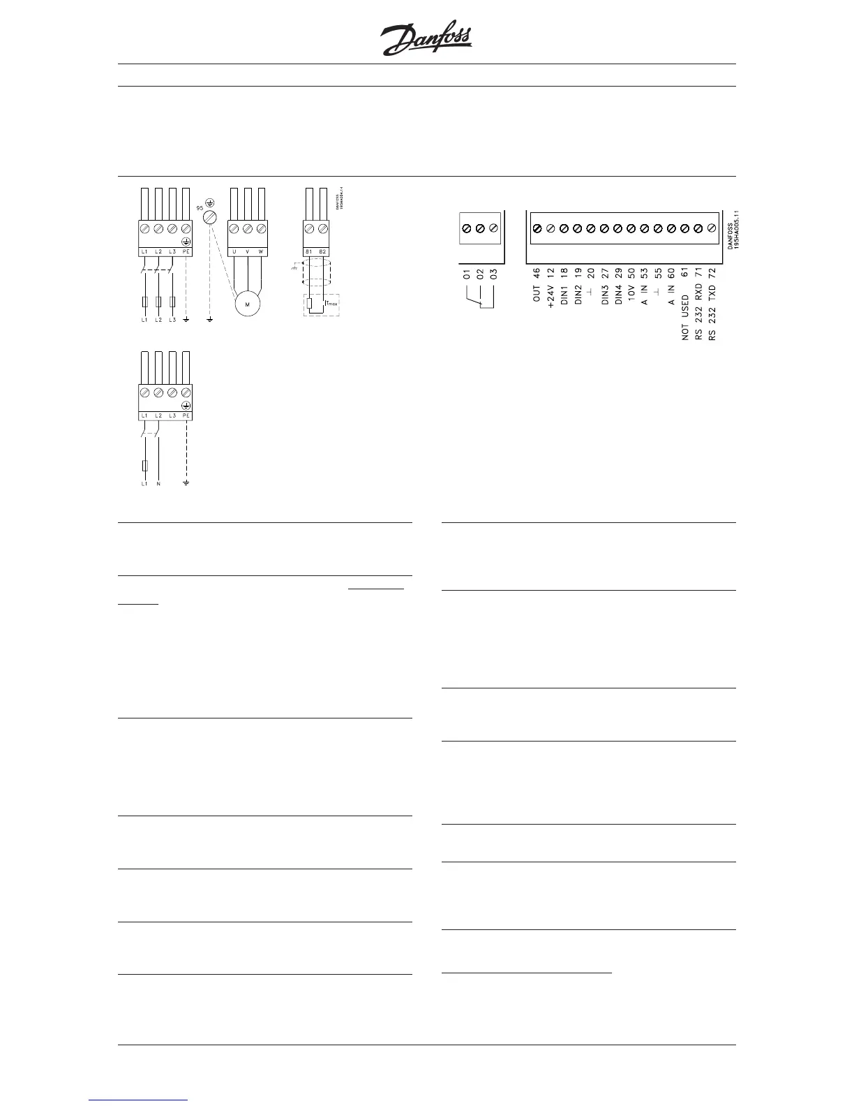
Survey of terminals
Below you will see a survey of all the terminals of a
VLT frequency converter (3 x 380-460 V).
After installation
Description of connection terminals
Terminal 12: Internal voltage supply
24 V DC activates digital inputs such as Start/stop,
Jog or Quick stop.
Terminal 18: Start/stop (Digital input)
When 24 V DC is applied the motor starts
on condit-
ion that
− digital input 27 (Quick stop) is connected
to 24 V DC.
− you have made no local stop command
(“Stop/reset” key).
− f
Max
is > 0 Hz.
− a reference signal has been given (see para. 402).
Terminal 19: Reversing (Digital input)
When 24 V DC is applied to terminal 19, the motor
starts reversing, either at once or after a stop com-
mand. If you have chosen pulse start in para. 402
(terminal 18), the start reversing function of para.
403 is automatically a pulse-activated function.
Terminal 20: Digital common
This terminal is the reference for all digital signals,
including bus.
Terminal 27: Stop (Digital input)
When you apply 0 V you can give different stop sig-
nals. See also para. 404.
Terminal 29: Jogging (Digital input)
This terminal allows you to activate a fixed
preprogrammed speed. See para. 405.
Terminal 46: Output
Using parameter 408 you can choose between
different output signals. The output is an open collector
output, and a pull-up resistor of min. 600 ohm must
therefore be connected to terminal 12 (+24 V).
Terminal 50: Internal voltage supply
With 10 V DC voltage you can set an analogue
control signal using a 1 kohm potentiometer with ter-
minal 55 as reference.
Terminal 53: Analogue control voltage
Using parameter 412 you can choose between 0 -
+10 V DC or +10 - 0 V DC analogue voltage. The ter-
minal is used together with terminals 50 and 55. The
voltage value determines the output frequency and
thus also the speed of the motor.
Terminal 55: Analogue common
Is used together with terminals 50 and 53 or together
with terminal 60.
Terminal 60: Analogue control current
Using parameter 413 you can choose between four
different input signals:
0-20 mA, 4-20 mA, 20-0 mA or 20-4 mA.
The current value determines the output frequency.
Terminal 61: Not used
Terminals 71-72: RS 232 port
Connect the terminals to a PC, if you want to control
the VLT frequency converter via PC software. Terminal
20 acts as digital common.
Terminals 81-82: Brake resistor
By means of these terminals you can connect the
brake resistor on units with brake function.
Note the live voltage 550 V DC.
The control signals and the terminals for the brake
module are described at the bottom of this page.
Mains Motor
Br.
■
■