Section Three
3 - 2
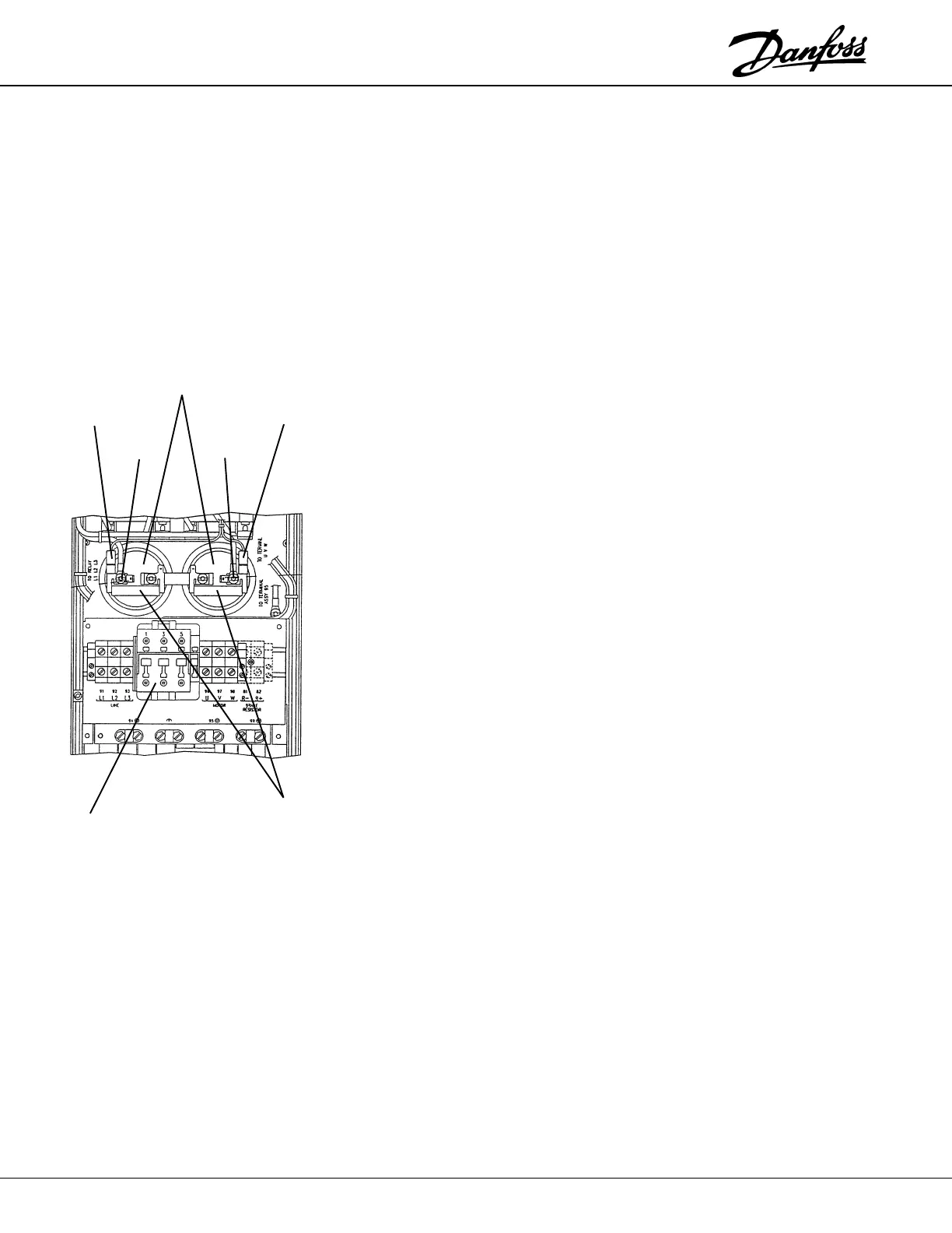
Red Lead
Black Lead
–UDC +UDC
STATIC TEST PROCEDURES
TESTING THE INPUT
RECTIFIER
DC Bus
Capacitors
Bus
Contactor
Balance
Resistors
VLT 3006-3022, 230V VLT 3508-3532, 230V
VLT 3011-3052, 380V/460V VLT 3516-3562, 380V/460V
1. Remove any plastic shields covering the DC Bus Capacitors and locate the
18 gauge red and black leads connected to the Bus Capacitor bus bars as
shown. These leads indicate the positive (+UDC) and negative (– UDC) DC
Bus test points. The number and location of the bus capacitors will vary
between units.
2. Connect the positive (+) meter lead to (+UDC). Connect the negative (–)
meter lead in turn to the terminals (1/L1), (3/L2), and (5/L3) as labeled on
the top side of the Bus Contactor. Each reading should be open.
3. Reverse the meter leads connecting the negative (–) meter lead to (+UDC)
and the positive (+) meter lead in turn to the terminals (1/L1), (3/L2), and (5/
L3) on the top side of the Bus Contactor. Each reading should read a diode
drop.
4. Connect the positive (+) meter lead to (–UDC). Connect the negative (–)
meter lead in turn to the terminals (1/L1), (3/L2), and (5/L3) on the top side
of the Bus Contactor. Each reading should show a diode drop.
5. Reverse the meter leads connecting the negative (–) meter lead to (–UDC)
and the positive (+) meter lead in turn to the terminals (1/L1), (3/L2), and (5/
L3) on the top side of the Bus Contactor. Each reading should show open.
Test completed.
Incorrect readings indicate a faulty rectifier module. See Removal and Replacement
Instructions on page 4-4 If the rectifier module is shorted, it is important to inspect
the Bus Charge Contactor. See page 3-3 for testing the soft-charge circuit.
 Loading...