3 - 1
Section Three
All tests will be made with a meter capable of testing diodes. Use a digital VOM
set on diode scale or an analog ohmmeter set on R x 100 scale. Before making
any checks disconnect all input power, motor and brake option connections.
CAUTION:
Allow sufficient time for the DC Bus to fully discharge before beginning
testing. The presence of bus voltage can be tested by setting your
voltmeter for 1000VDC and reading the voltage at the labeled terminals
shown in the drawings.
The purpose of making static tests on the input rectifier is to rule out failures in this
device, either shorted or open diodes. Failure of the rectifier module will usually
result in blown line fuses. It should be noted that blown input line fuses can also
be the result of shorts in the IGBT module(s) or a damaged bus capacitor. See
Testing the Inverter Section and Testing the Bus Capacitors. For measurements
where an open-circuit is expected the meter may show some initial continuity as
the DC Bus capacitors charge up. This is normal and to be expected.
VLT 3002-3004, 230V VLT 3502-3504, 230V
VLT 3002-3008, 380V/460V VLT 3502-3511, 380V/460V
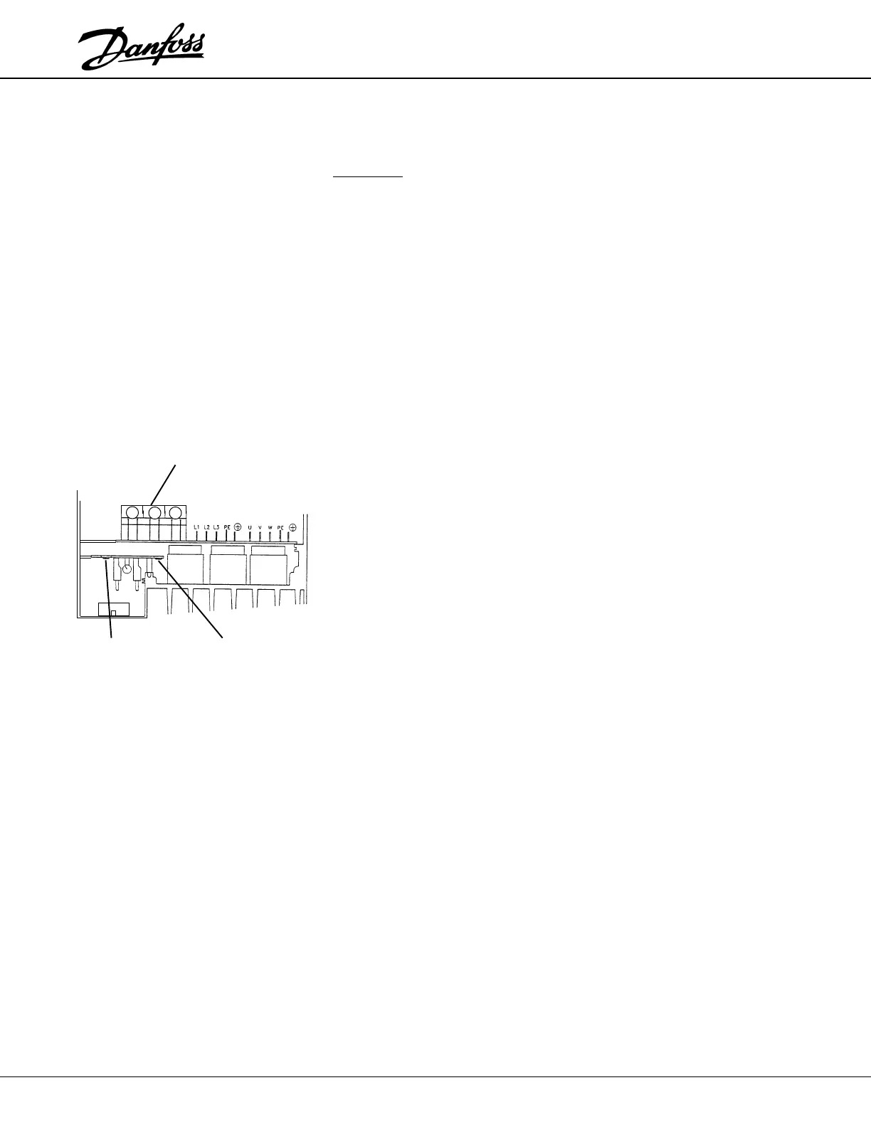
1. Remove the Control Card to expose the ILD Card. Locate the UDC connector
on the ILD Card (MK102). The red lead at the top side of the connector will
be used for the (+UDC) test point and the black lead at the bottom of the
connector will be the (–UDC) test point. The +UDC and –UDC fast-on
terminals on the DC Card (as shown) can also be used.
2. Connect the positive (+) meter lead to (+UDC). Connect the negative (–)
meter lead to terminals 91 (L1), 92 (L2), and 93 (L3) in turn. Each reading
should be open.
3. Reverse the meter leads connecting the negative (–) meter lead to (+UDC)
and the positive (+) meter lead to power terminals 91 (L1), 92 (L2), and 93
(L3) in turn. Each reading should show a diode drop.
4. Connect the positive (+) meter lead to the red lead (–UDC). Connect the
negative (–) meter lead to power terminals 91 (L1), 92 (L2), and 93 (L3) in
turn. Each reading should show a diode drop.
5. Reverse the meter leads connecting the negative (–) meter lead to the
(–UDC) and the (+) meter lead to power terminals 91 (L1), 92 (L2), and 93
(L3) in turn. Each reading should show open. Test is complete.
Incorrect readings could indicate a faulty Rectifier Module. See Removal and
Replacement Instructions. If there is an open circuit reading when a diode drop
reading is expected, see Testing the Soft Charge Circuit.
TESTING THE INPUT
RECTIFIER
STATIC TEST PROCEDURES
+UDC
–UDC
NTC
Resistors
 Loading...