3 - 7
Section Three
DYNAMIC TEST
PROCEDURES
TESTING FOR CURRENT
FEEDBACK
A current sensor is in line with each phase of the output. These hall effect devices
generate a current that is proportional to the current being drawn in each respective
motor phase. The VLT relies on this feedback for proper output waveform control
and for providing fault protection. Problems with the current sensors can cause
unstable operation, over current trips, and ground fault trips.
A simple test of these signals can be made with a voltmeter. The measured voltage
will be proportional to the current signal produced by each current sensor. At very
light loads the AC voltage signal may be no more than 100mV to 300mV. The
purpose of this test is to verify that all three sensors are functioning and that the
signals are approximately equal when compared to each other.
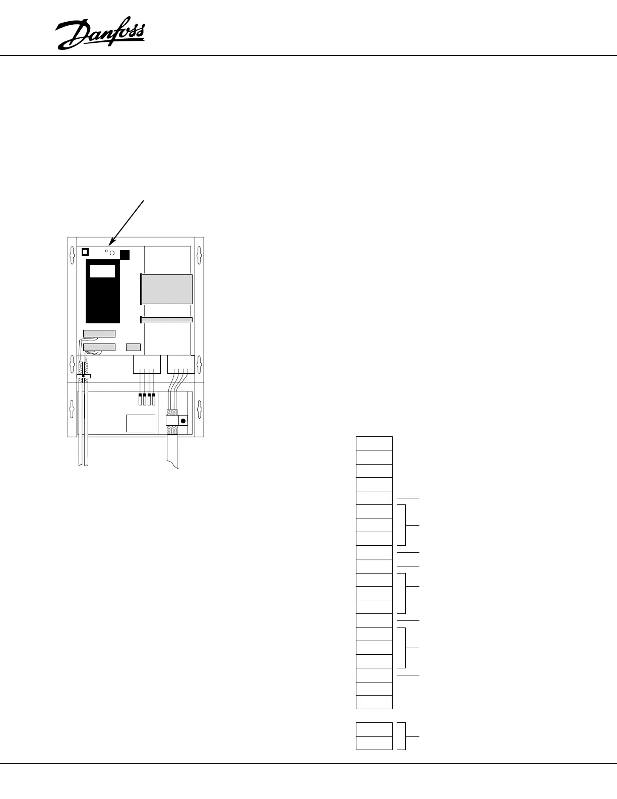
1. Apply power to the unit. Leave the unit in stop mode.
2. Using a DC voltmeter, connect the negative (–) meter lead to the Control
Card test point labeled GND. Connect the positive (+) meter lead in turn to
pins 4, 5, and 6 of the Control Card MK200 connector, (pin 1 of MK200 is on
the lower side, closest to the MK201 connector). All three readings should
be within 20 millivolts of zero.
3. Start the drive and bring the motor up to stable speed. Change the voltmeter
to read AC voltage and measure the Same signals at pins 4, 5, and 6 of
MK201. All readings should be approximately equal.
Severe imbalances in the readings indicate a faulty current sensor or an uneven
current draw by the motor. See "Testing for Output Phase Voltage Imbalance" on
page 3-6. (The current sensors will vary with unit size. Consult Appendix drawings
for assistance in finding component locations.)
GND
GND Test Point
+5V
+5V
+5V
+5V
INVOK
WP
VP
UP
SYNC
DISAB
COM
COM
COM
SIN
CR BW
CR BV
CR BU
VF B
+13V
–13V
+24V
COM1
20
19
18
17
16
15
14
13
12
11
10
9
8
7
6
5
4
3
2
1
2
1
FAULT LOGIC
PWM SIGNALS
SERIAL COMMUNICATION SIGNAL
RUN MODE LOGIC
COMMON FOR +13V, –13V, +5V
SAME AS "GND" TEST POINT
NOT USED
MOTOR CURRENT SIGNALS
DC BUS SIGNAL
SEPERATE CONTROL LOGIC
POWER SUPPLY
MK201 MK200
Control Card
Ribbon Cables
 Loading...