Appendix
7 - 5
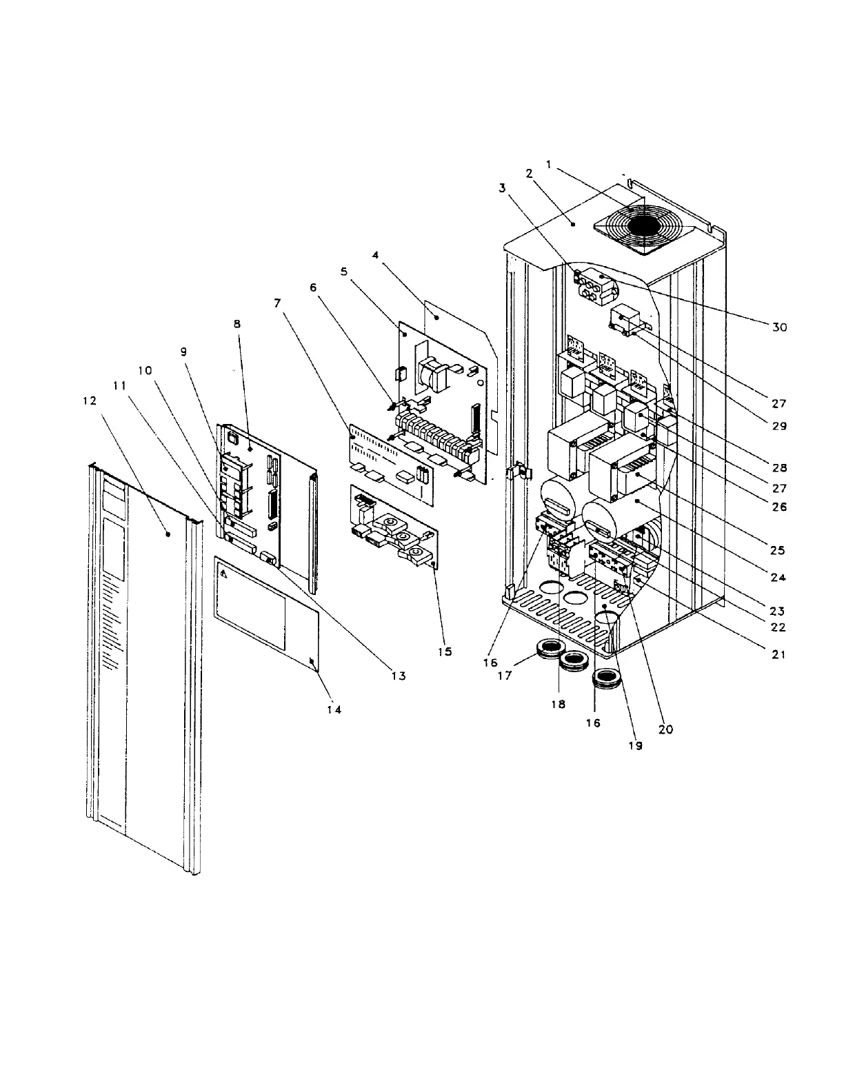
COMPONENT LOCATION
VLT 3006-3022, 230V VLT 3508-3532, 230V
VLT 3011-3052, 380/460V VLT 3516-3562, 380/460V
1. Top fan
2. Top Cover
3. Heat Sink Thermal Switch
4. Interface Insulator Foil (not on 230V)
5. Interface Card
6. Brake Control Card Support (not on VLT 3500)
7. Brake Control Card (not on VLT 3500)
8. Control Card
9. Display/Keyboard Unit
10. 10-Position Thermal Strip
11. 11-Position Terminal Strip
12. Front Cover
13. 5-Position Terminal Strip
14. Safety Shield
15. Relay Card
16. LINE/MOTOR Terminal Strip
17. Rubber Grommet
18. Bus Contactor
19. Bottom Cover
20. BRAKE Terminal Strip (not on VLT 3500)
21. RFI Option
22. Balance Resistor
23. Motor Coil
24. DC Bus Capacitor
25. DC Coil
26. Brake IGBT (not on VLT 3500)
27. Clamp Capacitor
28. IGBT Module
29. MOV
30. Rectifier Module
 Loading...