Pag. 21
Instruction Manual
EEnngglliisshh
Pag. 20
Danieli Automation - ID6100
The following table describes how to set Bank A
DIP-Switches to enable or disable the automatic
sensitivity control.
AAuuttoommaattiicc sseennssiittiivviittyy ccoonnttrrooll SSwwiittcchh::66
Disabled OFF
Enabled ON
55..55 BBaarr ppoossiittiioonn mmooddee sseettttiinngg
The analog output of the ID6100 photodetector
can be set to be relative to either the axis of the
bar (P1: middle-point between upper and lower
edges), or else the upper limit of the bar position
(P2, see figure 5).
If the first option is selected (axes of the bar) the
position is not dependent on bar diameter.
In the case that more than one bar is present at
any time, the upper limit of the bar position of
the highest bar will be indicated for the second
option (see figure 6).
The following table describes how to set Bank B
DIP-Switches to select if the analog ouput has to
be relative to the axis or the upper limit of the
bar.
PPoossiittiioonn mmooddee SSwwiittcchh::11
Axis of the bar OFF
Upper limit of the bar ON
Using the "upper limit" bar position mode, it is
possible to use the ID6100 as a position detec-
tor for the ends of bars of varying lengths, as
shown in Fig. 7.
NOTE: When all the settings have been made replace the
cover carefully. Check that the gasket is correctly positio-
ned and that the hermetic sealing has been re-establis-
hed.
P1
P2
P1
P2
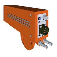
55 RReeffeerreennccee ppooiinntt ffoorr ppoossiittiioonn
ccaallccuullaattiioonn..
SSiinnggllee bbaarr iinn tthhee vviieewwiinngg ffiieelldd::
PP11:: AAxxiiss ooff tthhee bbaarr ((ppo
ossiittiioonn nnoott
ddeeppeennddeenntt oonn ddiiaammeetteerr))
PP22:: UUppppeerr lliimmiitt
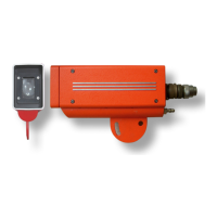
66 RReeffeerreennccee ppooiinntt ffoorr ppoossiittiioonn
ccaallccuullaattiioonn..
TTwwoo bba
arrss iinn tthhee vviieewwiinngg ffiieelldd
((sslliittttiinngg))::
PP11:: MMiiddddllee--ppooiinntt bbeettwweeeenn tthhee
uuppppeerr//lloowweerr lliimmiittss ooff tthhee ttwwoo bbaarrss.
.
PP22:: UUppppeerr lliimmiitt ooff tthhee hhiigghheesstt bbaarr..
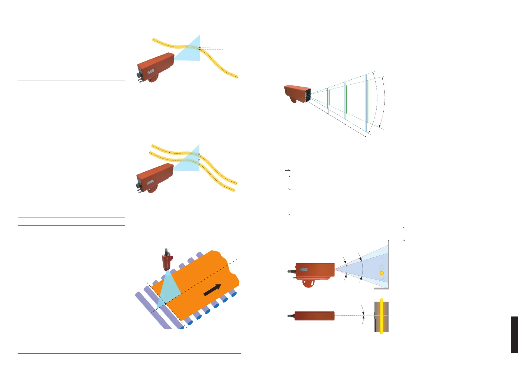
77 UUssiinngg IIDD66110000 ttoo mmeeaassuurree tthhee eeddggee
ppoossiittiioonn ooff wwiiddee hhoott bbooddiieess..
500
410
270
1230
820
540
810
45° 30°
1000
1500
88 MMaatteerriiaall ddeetteeccttiioonn
ppllaanneess aatt vvaarriioouuss
ddiissttaanncceess ((iinn mmmm))..
99 FFiieelldd ddeetteeccttiioonn::
vveerrttiiccaall//hhoorriizzoonnttaall..
45°
30°
0,5°
99
88
Vertical angle
Horizontal angle
Do not mount the photocell on structures
subject to vibrations.
It is recommended that the photodetector is
pointed downwards.
Figures 10 and 11 show examples of correct
and incorrect positioning.
66.. IINNSSTTAALLLLAATTIIOONN
For maximum reliability in detection, the unit must be mounted in an appropriate position, conside-
ring the detection field, as shown in figure 8.
66..11 PPoossiittiioonniinngg
Place a thin infrared source (e.g. an incande-
scent lamp with a screen, or a chop of reheated
rolled stock) in the center of the vertical viewing
range intended for the loop positions, then align
the detector vertically so as to obtain a position
analog output corresponding to approximately
50% of the selected output range (e.g., for a 0-
10V range, approx. 5 Volts).
In this way the correct vertical alignment is then
obtained.
Then check that the entire position range for
the loop (both upwards and downwards) is cove-
red by the detector's viewing field, and that the
output signal changes accordingly.
To position the unit correctly, the following points must also be considered:
If the position is too close to the objects then the photo detector can become overheated.
If the position is too far away, there is an increased risk of interference occurring between the
object to be detected and the photodetector.
External sources of light or infrared radiation (lights or windows, etc) should not be present in the
field of observation of the detector, figure 11.
In case of any interference of this type, it is recommended to provide the installation with appropria-
te screening, (see the example in figure 10).
Smoke, dust, steam or other bodies passing between the detector and the objects to be detec-
ted can cause detection to be missed.
 Loading...