PAGE 24 46210/46220-0998 <90-00036>
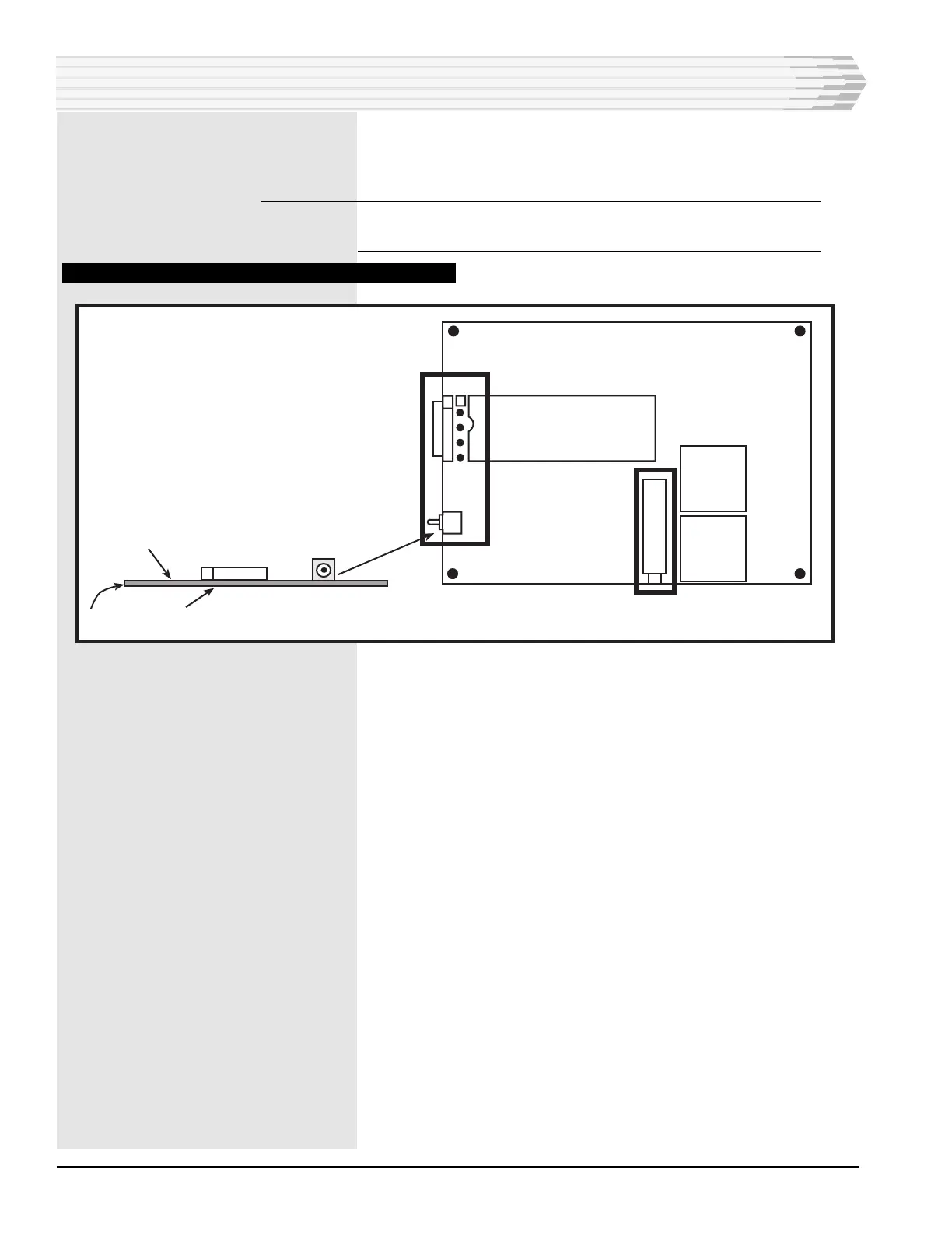
Place S1 in the NORM position (refer to Fig. 18).
Remove the dB meter.
NOTE: To check the transmit level without making an adjustment,
short pins R and S of column 32 instead of using S1.
FIG. 18 - 202 MODEMSUBASSEMBLY COMPONENT LOCATION
3. Generate one or more alarms and verify that they are reported
correctly to the alarm reporting equipment.
4. Clear the alarms and verify that they are reported correctly to the
alarm reporting equipment.
5. If the unit has controls, operate the controls and verify that they
work properly.
6. Checkout complete.
INSTALLATION
X1
1
S1
R8
S1
Test
Component Side
Solder Side
Normal
PC Board