46210/46220-0998 <90-00036> PAGE 3
LEDs indicate:
♦ If the unit is transmitting or receiving data through the mas-
ter or auxiliary ports,
♦ If the microprocessor is operating,
♦ If the power is on,
♦ If the power fuse has blown.
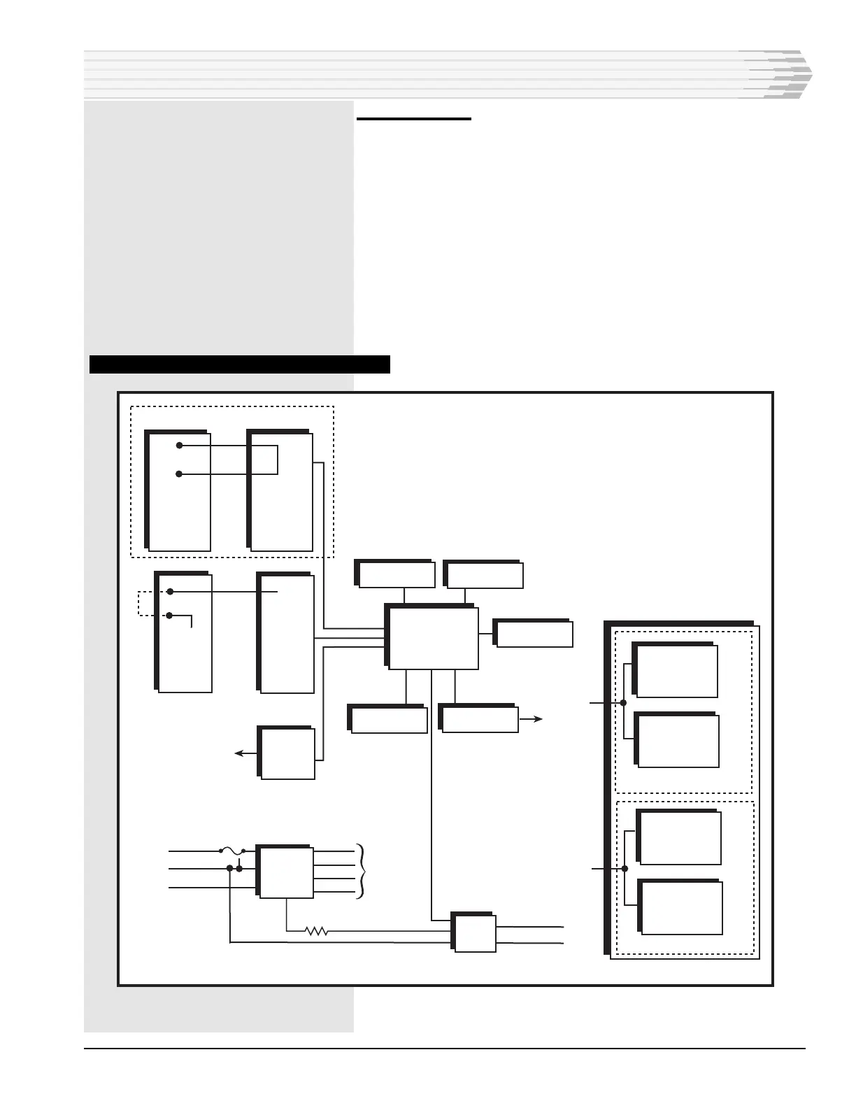
The unit operates on -21 to -56 VDC.
In addition to the fuse failure LED, an external light or bell can
be connected to the power supply to indicate fuse failure.
FIG. 1 - 46210/46220 FUNCTIONAL SCHEMATIC
CIRCUIT DESCRIPTION
TYPICAL CONTROL
OUTPUT
WIREWRAP
TERMINAL
BLOCK
CONTROL
INTERFACE
BOARDS
N.O. RELAY
46220
ONLY
X
X
N.O.
RELAY
TIE
TO
GND
WIREWRAP
TERMINAL
BLOCK
TYPICAL
ALARM
INPUT
ALARM
INTERFACE
BOARDS
CLOCK
7.37 MHZ
WATCHDOG
CIRCUIT
MEMORY
SWITCHES
UART
TO
1 OR 2
16-BIT
MICROPROCESSOR
AND
ASSOCIATED
CIRCUITRY
POWER
SUPPLY
LED
DISPLAY
AUXILIARY
PORT
RS-422
MASTER
PORT
RS-422 / 485
AUXILIARY
PORT
RS-422 / 485
MASTER PORT
OPTIONAL
SUBASSEMBLY
202 MODEM
OR RS-232
WITHOUT OPTIONAL
SUBASSEMBLY
WITH OPTIONAL SUBASSEMBLY
WIRE-WRAP TERMINAL BLOCK
1
2
P1-1
THROUGH
P1-16
NOT
USED
+5 VDC
-5 VDC
+12 VDC
-12 VDC
TO
CIRCUITRY
-12 VDC
TB1 - 1
TB1 - 2
TB1 - 3
- BATT
FUSE
ALARM
GND
1A
uP
POWER
FUSE
XMT / RCV (MAS)
XMT / RCV (AUX)
NOTE: When the unit is used without an optional
communications subassembly, the auxiliary port has an
RS-422 interface and the master port has an RS-422/485
interface. When the unit communicates via an optional
communications subassembly, the port with the subassembly
installed becomes the master port and the auxiliary port
communicates via an RS-422/485 interface. The auxiliary
port with the RS-422 interface only is not used.