PAGE 32 46210/46220-0998 <90-00036>
15. Verify proper operation of alarms and controls.
16. Power Supply/CPU replacement complete.
INTERFACE BOARD SUBASSEMBLY
To replace a subassembly:
1. Open the unit (refer to Fig. 23).
2. Pull the power supply and CPU boards down from the other cir-
cuitry (refer to Fig. 24).
3. Remove power by pulling out the fuse. The power connector at TB1
does not need to be disconnected.
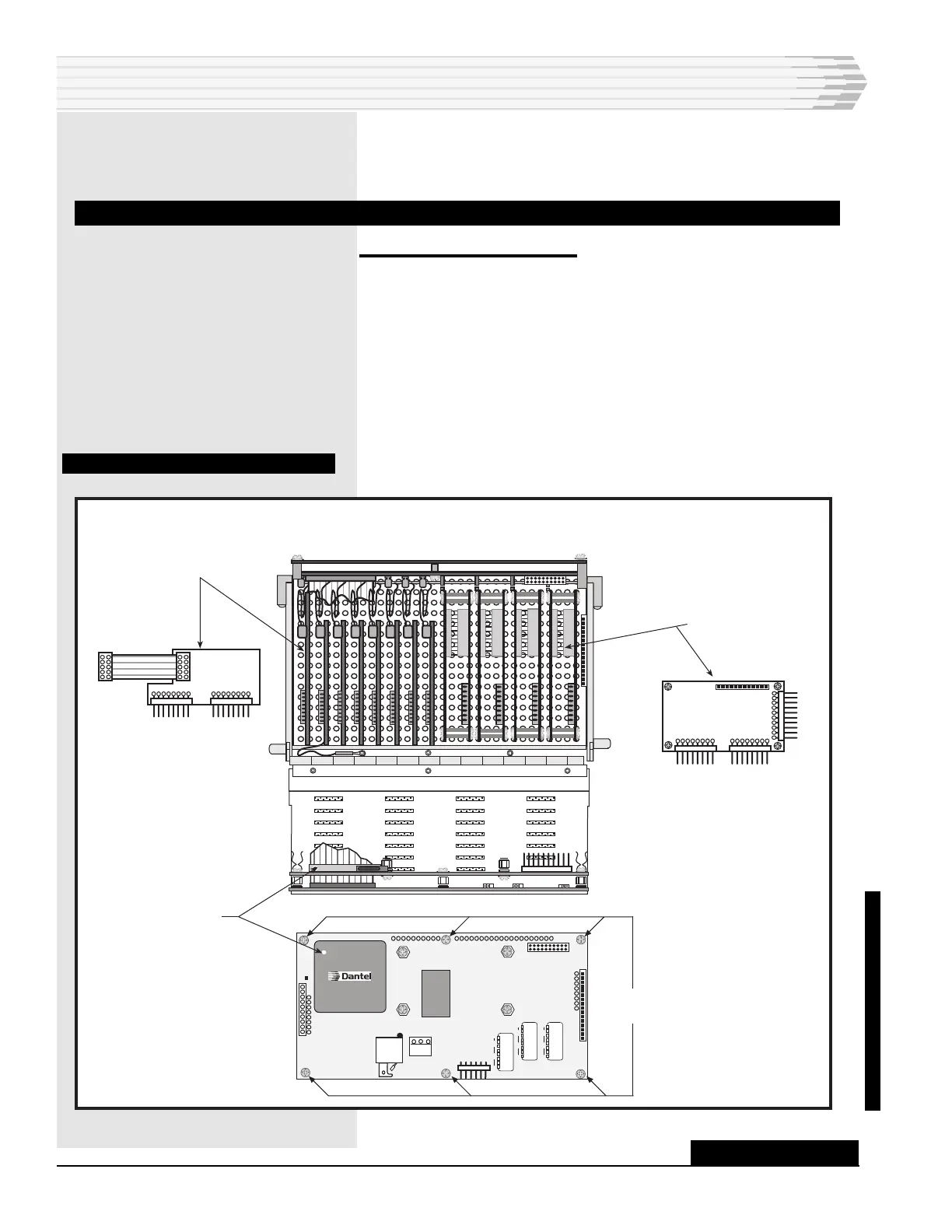
4. Refer to Fig. 26 for the location of the Interface Board subassem-
blies.
FIG. 26 - SUBASSEMBLY LOCATIONS
SUBASSEMBLY REPLACEMENT
CONTINUED . . .
Control Interface
Board
Power supply
AB8-00415-04
Made In USA
Power Supply
CPU Board
Interface
Board
81
OFF
81
OFF
81
OFF
Six screws holding
two halves together.
UPDATED