13
062367 • Version 1.0 • 14.02.2011
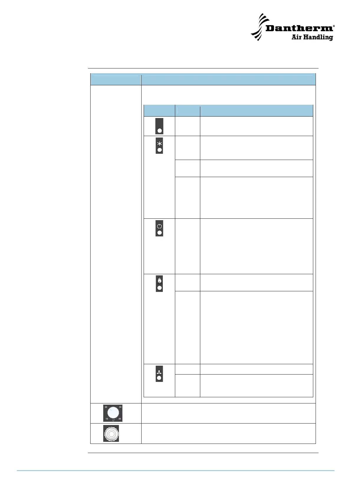
Description of the control board, continued
Part/function, con-
tinued
Part Function
e
Indicator
lamps
On the operator panel there are 4 control lamps, indicating the
following from left to right:
Symbol Color Description
- IR connection to serial port. For Dan-
therm service technician only
Green Cooling circuit is operating to lower tem-
perature.
Normal operation is green
Yellow The unit is operated inefficiently.
This will self reset in time
Cooling
Red The compressor current draw is outside
specified window.
(indicating a faulty compressor)
This will reset when functions switch is
briefly switched to off position
Power
Green Always green, provided there is 230 V
AC connected to the unit.
Note:
Also green when the functions switch is
in Off position
Must be completely off when servicing
unit/changing filter
Green Indicating the heater coil is working to
raise temperature
Heating
Red The heater coil current draw is outside
specified window.
(indicating an open circuit like OT fault)
This will reset when functions switch is
briefly switched to off position, and/or the
OT reset button is depressed.
OT fail:
Overheat thermostat failure. See also
section “Fault finding guide”, page 33
Green whenever one or both fans are running
Fan op-
eration
Red One or both fans have a defect chasing
the current draw out of specified window
f
Temperature dial for room temperature
g
Power cable
 Loading...