GENERAL SAFETY RULES
WARNING: Unskilled personnel should never be allowed to assemble,
repair or adjust the equipment, and all necessary precautions must be
taken to prevent accidents before starting work: power supply must
be disconnected (including backup batteries if present). Any use of
this product that is not intended by this instruction booklet and/or any
unauthorised modification to the product or its components relieves
DASPI of any liability arising from consequent damage or injury to
property, people or animals. This product is not suitable for installation
in explosive atmospheres. Keep this handbook carefully, attaching
it to the technical installation leaflet and storing it place where it is
available anyone who may need it and make sure said personnel are
aware of this.
TYPE OF PRODUCT
The SIGILE electronic control unit has been designed to control a
SKY C 24 Vdc model motor for spring overhead or sectional doors.
It is provided with deceleration, electronic clutch (adjustable for both
opening and closing), incorporated receiver, coupling for extractable
receiver and soft start function to ensure longer wear for the mechanical
parts. The control unit has a programmable input for the safety devices,
2 buttons with “person present” operation (for calibrating the limit
switches), a fixed working time of 60 seconds and courtesy light timed
at 90 seconds. DASPI will assume no liability for any unintended or
improper use of the SIGILE control unit.
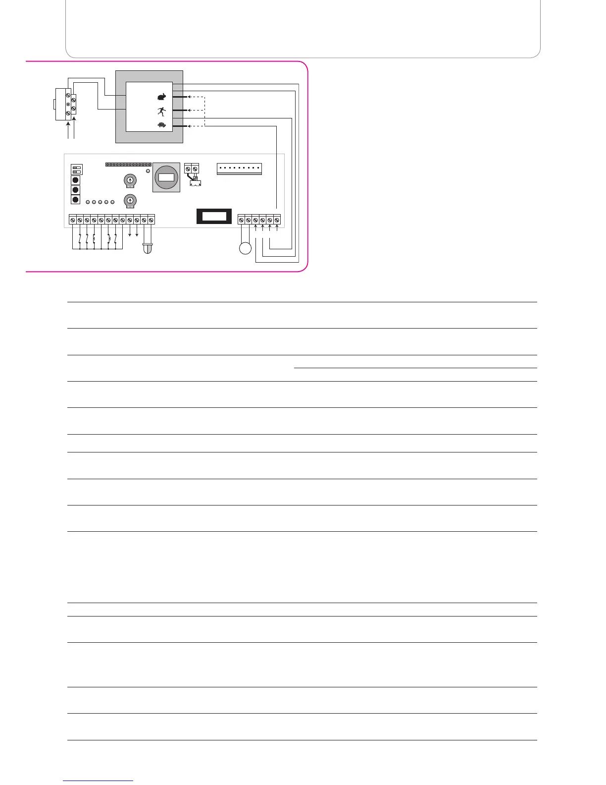
DESCRIPTION OF THE MAIN COMPONENTS
F1
8A fuse to protect 24 V accessories (motor, warning
lamp, courtesy light and 24V output)
P.CLOSE
Button for ‘person present’ closing (calibrating the
closing limit switch) during programming used to select
type of safety device (sensitive edge or photocell).
F2
2A Fuse for protecting 220V transformer primary
P.OPEN
Button for ‘person present’ opening (calibrating the
opening limit switch) during programming used to
adjust automatic closing time.
SW1
For selecting shared operation
/ pre-flashing
CLOSE
Adjustment of motor force during closing
OPEN
Adjustment of motor force during opening
RX
Connector for extractable receiver
J1 Integrated radio module
SET
Button for entering programming
PL1 Courtesy light (24Vdc max 10W)
LED’s indicating status of board input (can be checked after powering the control panel)
F.CH
Indicates status of closing limit switch, N.C. contact,
normally on
START
Indicates status of start control input, N.O. contact,
normally off
F.AP
Indicates status of opening limit switch, N.C. contact,
normally on
SAFE
Input for safety devices (see instructions for selecting
the type of device)
STOP
Indicates status emergency stop input, N.C. contact,
normally on
DL1
Displays programming status (radio learning,
automatic re-closing and type of safety device)
If the above does not tally, check the connections and make sure the various connected devices are working properly.
PROGRAMMING AND ADJUSTMENTS TO THE BOARD
The control unit should always be programmed with the closing limit switch occupied (the door is closed) or after powering the control unit and
before the START control.
PROGRAMMING SW1:
OFF ON
SW1/1
Shared operation disabled
Shared operation enabled (during opening and during automatic closing
time, the control unit does not accept start commands)
SW1/2
Pre-flashing disabled
Pre-flashing enabled (the lamp starts to flash 3 seconds before the
motor starts)
ADJUSTING THE TRIMMER:
CLOSE
Adjusts motor torque during closing, after crossing the preset threshold the motor stops and reverses for 2 seconds
(clockwise to increase, anti-clockwise to decrease) it is OFF during deceleration.
OPEN
Adjusts motor torque during opening, after crossing the preset threshold the motor stops and reverses for 2 seconds
(clockwise to increase, anti-clockwise to decrease) it is OFF during deceleration.
S I G I L E / E R X E L E C t R o n I C Co n t R o L u n I t
 Loading...