
R
Ruben PerkinsJul 31, 2025
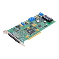
Why Data Translation DT3000 Control Unit board does not respond?
- CChristopher HughesJul 31, 2025
There are several potential reasons why your Data Translation Control Unit board might not be responding. First, the board configuration could be incorrect; check your device driver to ensure the board name and type are correct. Second, the board might be incorrectly aligned in the PCI expansion slot; ensure the DT3000 Series board is in a PCI slot and correctly seated. Third, an interrupt conflict might exist, especially between a PCI device and a device plugged into the ISA bus; try changing the interrupt setting on the ISA device. Finally, an interrupt conflict can occur if a PCI device wasn't designed to share interrupts; select a different interrupt for each PCI slot in the PCI BIOS.