This product is covered by one or more of the following patents.
European Patent 1,111,690 B1
S51-PA/PR SERIES
INSTRUCTION MANUAL
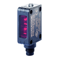
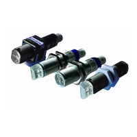
CONTROLS
OUTPUT LED (S51-…A00/B01/C01/C10/F00)
The yellow LED ON indicates that the NO output status is closed.
POWER ON LED (S51-…G00)
The green LED indicates that the sensor is operating.
TRIMMER (S51-…B01/C01)
The trimmer can be used to adjust sensitivity; the operating distance
increases turning the trimmer clockwise.
WARNING: The trimmer rotation is limited to 270°.
Do not apply excessive torque beyond the maximum and minimum
positions (max 40 Nmm).
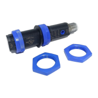
INSTALLATION
The sensor can be fixed by means of the M18x1 threaded body through a
18mm hole, using the specific washer and the two CH.24 nuts (1.5Nm
maximum tightening torque) or CH.22 nuts, h=8mm, (2Nm maximum
tightening torque) enclosed. Alternatively, the sensor can be mounted
through the two housing’s holes using two screws (M3x22 or longer)
and washer.
Amongst the various possible solutions, we suggest to choose the
combination that offers the best visibility of the signalling LEDs and the
easiest access to the trimmer.
Various orientable fixing brackets are available
to ease the sensor positioning (please refer to
the accessories listed in the general
catalogue). The operating distance is
measured from the front surface of the sensor
lens.
C models: To improve the detection, the object
has to be moved closer or further away from the front surface of the
sensor lens.
In case of lateral translation, the object must move as indicated in the
figure.
CONNECTIONS
The connections are compliant to the EN 60947-5-2 standard.
* in case of white wire or pin 2 not connected the sensor works in LIGHT
mode for proximity models (C01/C10/C20) and in DARK mode for
retroreflex (A00/B01) and receiver (F00).
M12 CONNECTOR
24
=
N°.2 Ø3.8
=
2.5
=
=
3.8
2
STABILITY LED
M12
10
15
M18x1
1.5
14
3.5
24
=
M12
3.5
1.5
2
=
3.8
14
12
10
14.5
N°.2 Ø3.8
TRIMMER
15
mm
14
=
M18x1
10
Ø4
25
25
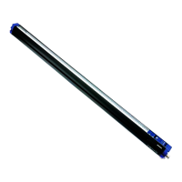
RADIAL VERSION
TRIMMER
OUTPUT LED
STABILITY LED
OUTPUT LED
OUTUPT LED
STABILITY LED
57
42
24
without trimmer
L
X
X1
M O D E L S
with trimmer
67
43
34
L
X1
X
AXIAL VERSION
X
X1
L
6°
14.5
14.5
CABLE VERS.
M O D E L S
without trimmer
L
X
X1
79
43
46
with trimmer
69
42
36
CABLE VERS.
STABILITY LED
OUTPUT LED
10
Ø4
CH.24 PLASTIC NUTS CH.22 PLASTIC NUTS
10 … 30 Vdc (limit values)
Current consumption
(output current excluded):
N.O.; PNP or NPN (short circuit protection)
Output saturation voltage:
OUTPUT LED (YELLOW) mod.G00 excluded
POWER ON LED (GREEN) (mod.G00)
sensitivity trimmer (mod.B01/C01)
500 Vac 1 min., between electronics and housing
>20 M 500 Vdc, between electronics and housing
Operating distance
(typical values):
A00: 0.1…3.5 m on R2
B01: 0.1…2.5 m on R2
C01: 1…40 cm
C10: 0…10 cm
F00/G00: 0…18 m
A00: 0.1…2.5 m on R2
B01: 0.1…2.0 m on R2
C01: 1…30 cm
C10: 0…8 cm
F00/G00: 0…15 m
RED (660 nm) (mod.B01) / INFRARED (880 nm) (mod.A00/C01/C10/G00)
0.5 mm amplitude, 10 … 55 Hz frequency, for every axis (EN60068-2-6)
11 ms (30 G) 6 shock for every axis (EN60068-2-27)
white wire or pin 2 connected to +10…30V LIGHT mode; to 0V DARK mode
white wire or pin 2 not connected LIGHT mode (mod.C01/C10);
DARK mode (mod.A00/B01/F00)
2 m cable 4 mm / M12 - 4 pole connector
75 g. max. cable vers. / 25 g. max. connector vers.
I I 3G EX nA II T6 ;
I I 3D EX tD A22 IP67 T85°C
SETTING
Setting of S51-…A00/B01
Position the sensor and reflector on opposite sides.
Moving the sensor both vertically and horizontally, determine the power
on and off points of the yellow LED (OUT) and then mount the sensor in
the middle of the points defined.
B01 Model: Turn the sensitivity trimmer to the maximum position.
If necessary reduce sensitivity in order to detect very small targets. In
order to improve alignment, repeat the procedure detailed above whilst
progressively reducing the sensitivity.
Setting of S51-…F00/G00
Position the sensors on opposite sides.
Move the sensor both vertically and horizontally, determine the power on
and off points of the yellow LED (OUT) and then mount the sensor in the
middle of the defined points.
Setting of S51-…C01
Turn the sensitivity trimmer to minimum: the yellow LED
is OFF.
Position the target to detect in front of the sensor.
Turn the sensitivity trimmer clockwise until the yellow
LED turns ON (Target detected state, pos.A).
Remove the target, the yellow LED turns OFF.
Turn the sensitivity trimmer clockwise until the yellow LED turns ON
(Background detected state, pos.B).
The trimmer reaches the maximum level if the background is not
detected.
Turn the trimmer to the intermediate C position, between the two A and B
positions.
Setting of S51-…C10
The operating distance range of these sensors is factory preset: please
consider this feature when positioning.
TEST FUNCTION (S51-…G00)
The TEST+ and TEST- inputs can be used to inhibit the emitter and
verify that the system is correctly operating.
The receiver output should switch when the test is activated while the
beam is uninterrupted. The inputs activating voltage range is 10 … 30
Vdc, whilst respecting the polarity.
The emission is switched off connecting TEST+ to Vdc and TEST- to
0V.
EX-II-3-D T6
Temperature class:
Max. Internal capacitance:
Datalogic S.r.l.
Via S. Vitalino 13 - 40012 Calderara di Reno - Italy
Tel: +39 051 3147011 - Fax: +39 051 3147205 - www.datalogic.com
Helpful links at www.datalogic.com: Contact Us, Terms and Conditions, Support.
The warranty period for this product is 36 months. See General Terms and Conditions of
Sales for further details.
For information about the disposal of Waste Electrical and Electronic
Equipment (WEEE), please refer to the website at www.datalogic.com.
© 2007 - 2020 Datalogic S.p.A. and/or its affiliates ALL RIGHTS RESERVED. Without
limiting the rights under copyright, no part of this documentation may be reproduced, stored in
or introduced into a retrieval system, or transmitted in any form or by any means, or for any
purpose, without the express written permission of Datalogic S.p.A. and/or its affiliates.
Datalogic and the Datalogic logo are registered trademarks of Datalogic S.p.A. in many
countries, including the U.S.A. and the E.U. All other trademarks and brands are property of
their respective owners. Datalogic reserves the right to make modifications and improvements
without prior notification.
826002973 Rev.E