Do you have a question about the Datalogic IO-Link TL46 and is the answer not in the manual?
Describes how to position the sensor using housing holes or M5 threads and how to orient the connector.
Explains how operating distance is measured and how to adjust beam direction for better mark detection.
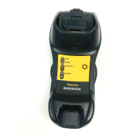
Details the function of the yellow Output LED and green Ready LED, including overload indication.
Explains the function of the Mark and Background push-buttons for acquisition.
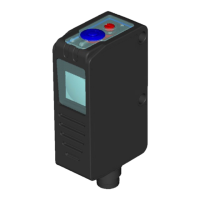
Describes the yellow Output LED, 4-digit display, and green Ready LED status indications.
Explains the function of the green Delay LED and Keylock LED.
Provides detailed dimensional drawings for the WH model.
Lists key technical data including power supply, output characteristics, response time, and operating conditions.
Details environmental ratings, material specifications, and certifications like ATEX.
Explains how to use dynamic acquisition for moving marks and the button presses involved.
Describes what happens when dynamic acquisition fails and how to retry.
Describes how to adjust the switching threshold using push-buttons.
Outlines the steps for color detection and handling failures.
Explains how to adjust the sensor's tolerance level.
Details how to adjust the sensor's hysteresis level.
Describes how to switch between Mark and Color modes.
Explains how to configure the output as normally open or normally close in Color mode.
Guides on how to navigate the parameter menu using push-buttons.
Details the procedure for setting the output delay ON time.
Explains how to configure the output delay OFF time.
Describes how to set the output modes for Output 1 and Output 0.
Explains how to set the display reading direction.
Describes how to turn the display off for power saving.
Explains how to select and load previously saved job configurations.
Guides on saving current sensor settings into a job.
Details how to reset the sensor to its factory default parameters.
Explains how to use the remote input for acquisition functions.
Describes the use of the DARK/LIGHT input for dynamic acquisition mode.
Explains how delay settings can be controlled via input signals.
Describes how output overload is signaled.
Details IO-Link revision, SIO mode, cycle time, and transmission rate.
Information on process data length and M-sequence capability.
Information on data storage capabilities and supported access locks.
Describes the device profile and function class characteristics.
Lists ISDUs that are not saved via Data Storage.
Details the configuration of device access locks.
Lists various profile characteristics.
Provides details on the PDInput descriptor.
Details vendor name, product name, ID, and text.
Includes serial number, hardware, and firmware revision details.
Describes application-specific tags and function tags.
Details process data input and sampled analog signal values for different emissions.
Information on actual, min, max device temperatures and thresholds.
Details operating hours, maintenance hours, and current device status.
Provides information on pending events and emitter status.
Covers RGB emission selection and signal quality metrics.
Explains the quality of teach threshold.
Details teach-in channel selection and teach-in results.
Configuration of switching thresholds for SSC1 and SSC2.
Settings for C/Q pin and DO pin configuration for SSC1 and SSC2.
Explains how to select the sensor's sensitivity.
Configuration of color emission thresholds and tolerance.
Details the configuration of delay ON and delay OFF settings.
Describes how to configure the output type (PNP, Push Pull).
Explains the configuration for input functions (white and grey wires).
Details how to select between Mark and Color modes.
Lists commands for single value teach, TP1, TP2, and dynamic detection start/end.
Commands for restoring factory settings and confirming maintenance.
Commands for disabling/enabling emission and start/stop ping.
Lists event codes, names, modes, types, and device status.
Shows product name and ID mapping.
Indicates the status of the switch counter threshold reached.
Configuration settings for the switch counter mode, trigger, and threshold.
Details switch counter values and counting direction.
Illustrates the output switching, counter value, and threshold for static down counting.
Shows output switching, counter value, and threshold for auto down counting.
Illustrates the output switching, counter value, and threshold for static up counting.
Shows output switching, counter value, and threshold for auto up counting.
Lists events that can trigger a timestamp.
Provides details on timestamp latency and resolution.
Information on the timestamp list format and synchronization value.
Describes the flag for new timestamp events.
Commands to reset timestamp application and clock counter.
Commands for timestamp synchronization and resetting the new event flag.
How to load and select saved job configurations.
Procedure for saving current job settings and teach-in values.
Reports maximum vibration values during the product's lifetime on X, Y, and Z axes.
Details actual vibration values and autotuning values for X, Y, Z axes.
Configuration of the vibration threshold for event generation.
Reports actual tilt (roll, pitch, yaw) and autotuning values.
Configuration of the tilt threshold for event generation.
Details shock values and autotuning values for X, Y, Z axes.
Configuration of the shock threshold for event generation.
Command to take a "photo" of vibration and tilt values.
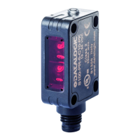
Explains the function of the yellow Output LED and green Ready LED.
Describes the function of indicator arrows and push-buttons.
Details how to position the sensor and orient the connector block.
Explains operating distance measurement and beam direction adjustment.
Provides detailed dimensional drawings for the sensor.
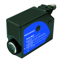
How to adjust sensor sensitivity using the knob.
Explains the function of the light/dark switch.
Procedure for setting up mark and background detection.
Lists key technical data including power supply, output specs, and response times.
Details environmental ratings, material, protection, and certifications.
Shows wiring for analog output and power supply.
Illustrates connections for delay signal and output signal.
Explains how the analog output voltage is proportional to the received signal.
Describes how delay setting extends active output duration for shorter pulses.
Details how to activate and deactivate the delay function.
Describes the signal for output overload.
Explains the function of the yellow Output LED and green Ready LED.
Describes the function of the Mark and Background push-buttons.
Procedure for setting up mark and background detection.
How to use dynamic setting for moving targets and DARK/LIGHT mode.
Explains how the analog output voltage is proportional to the received signal.
Describes how delay setting extends active output duration for shorter pulses.
Details how to activate and deactivate the delay function.
Explains how to change the output configuration between PNP and NPN.
Describes the signal for output overload.
Details how to position the sensor and orient the connector block.
Explains operating distance measurement and beam direction adjustment.
Provides detailed dimensional drawings for the sensor.
Lists key technical data including power supply, output specs, and response times.
Details environmental ratings, material, protection, and certifications.
Shows wiring for analog output, power supply, and remote input.
Illustrates connections for the NPN output signal.
Steps for setting up mark and background detection.
How to use dynamic setting for moving targets and DARK/LIGHT mode.
Outlines the steps for color detection.
Guides on navigating the parameter menu using push-buttons.
Describes the yellow Output LED and green 4-digit display.
Explains the status indications for Ready, Delay, and Keylock LEDs.
Lists the push-buttons for adjustment and setting.
Details how to position the sensor and orient the connector block.
Explains how to adjust the sensor's tolerance level.
Details how to adjust the sensor's hysteresis level.
Describes how to adjust the switching threshold.
How to configure the sensor in Mark or Color mode.
How to configure the output as normally open or normally close in Color mode.
Describes the signal indicating digital output overload.
Explains the output delay activation after mark entry into the detection area.
Guides on how to set the DELAY ON function using the parameter menu.
Details how to reset the sensor to its factory default parameters.
Explains how to save parameter settings using the SAVE function.
Explains how the remote input performs acquisition functions.
Details how remote signal duration determines acquisition type.
Describes the use of the DARK/LIGHT signal for dynamic detection mode.
Explains how delay settings can be controlled via input signals.
Lists key technical data including power supply, output specs, and response times.
Details environmental ratings, material, protection, and certifications.
| Series | TL46 |
|---|---|
| Product Category | Accessories |
| Type | IO-Link |
| Model | TL46 |
| Connection | IO-Link |
| Protection Rating | IP67 |