DELAY ON setting
The DELAY ON represents the output delay activation after the reference mark has
entered the detection area. The delay avoids the detection of events that occur rapidly.
An example can be a mark with shaded colours (light-dark-light) that can be detected
twice.
Select “dLOn” in the parameter menu to set the DELAY ON function.
The parameter programming is accessed by pressing .
The previously set delay value appears on the display.
Pressing or the delay value is increased or decreased by one step of 1 ms until
a maximum delay of 100ms. Keeping or pressed, the delay value is increased or
decreased by incremental steps. The setting of a delay different from zero is signalled by
the DELAY LED on. Press to confirm the value and return to the parameter menu.
DELAY OFF setting
The DELAY OFF represents the output delay deactivation after the reference target has
left the detection area.
The delay extends the output activation allowing slower system interfacing with sensors
to detect shorter pulses.
Select “dLOF” from the parameter menu to set DELAY OFF function.
The parameter programming is accessed by pressing .
The previously set delay value appears on the display.
Pressing or the delay value is increased or decreased by one step of 1 ms until
a maximum delay of 100ms. Keeping or pressed, the delay value is increased or
decreased by incremental steps. The setting of a delay different from zero is signalled by
the DELAY LED on. Press to confirm the value and return to the parameter menu.
UP/DOWN DISPLAY setting
The selection of the UP/DOWN display sets the reading direction on the
display.
Select “dSUP” or “dSdn” in the parameter menu to set the UP or DOWN
direction.
Press to switch the reading direction previously set.
ON/OFF DISPLAY setting
Turn off the display during normal operation to save power consumption.
Setting the OFF mode when the sensor is normally functioning, the display turns
OFF. It turns on for 5s after a keyboard command. Select “dSOn” or “dSOF” in the
parameter menu to set the display ON or OFF.
Press to switch the display mode previously set.
RESET of default parameters
Select “rSEt” in the parameter menu to reset the default parameters.
The “rSEt” text blinks when pressing .
Releasing the push-button the sensor returns to normal functioning.
The default reset parameters are:
NOTE: if the parameters are reset before turning the sensor off, when repowered
the “rSEt” text blinks on the display for 3s before returning to normal
visualisation.
Saving parameter set - “SAVE”
Select “SAVE” to save the parameter setting
The parameters are saved pressing . The display returns to normal
visualisation after releasing the button.
NOTE: Set the data, the operator exits from the menu using the “SAVE” or
“RESET” function. If these operations are not carried out 30s after the last setting,
the sensor returns to normal mode saving the parameters changed.
ACCESSORY FUNCTIONS
REMOTE INPUT
The REMOTE signals carries out the acquisition functions without using the push-
button. The REMOTE wire connected to +Vdc is equal to pressing the push-button.
Whereas, if the REMOTE wire is connected to GND or not connected, it is equal to not
pressing the push-button.
- The duration of the REMOTE wire connection to +Vdc determines the acquisition
type:
MARK MODE
COLOR MODE
DARK/LIGHT input (only in MARK mode)
The DARK/LIGHT signal allows the operator to select the DARK/LIGHT
operating mode for dynamic detection.
In the LIGHT mode, the output is active with light marks on dark backgrounds.
In the DARK mode, the output is active with dark marks on light backgrounds.
The connection of the DARK/LIGHT wire to Vdc sets the DARK mode.
If connected to 0V or not connected set the LIGHT mode.
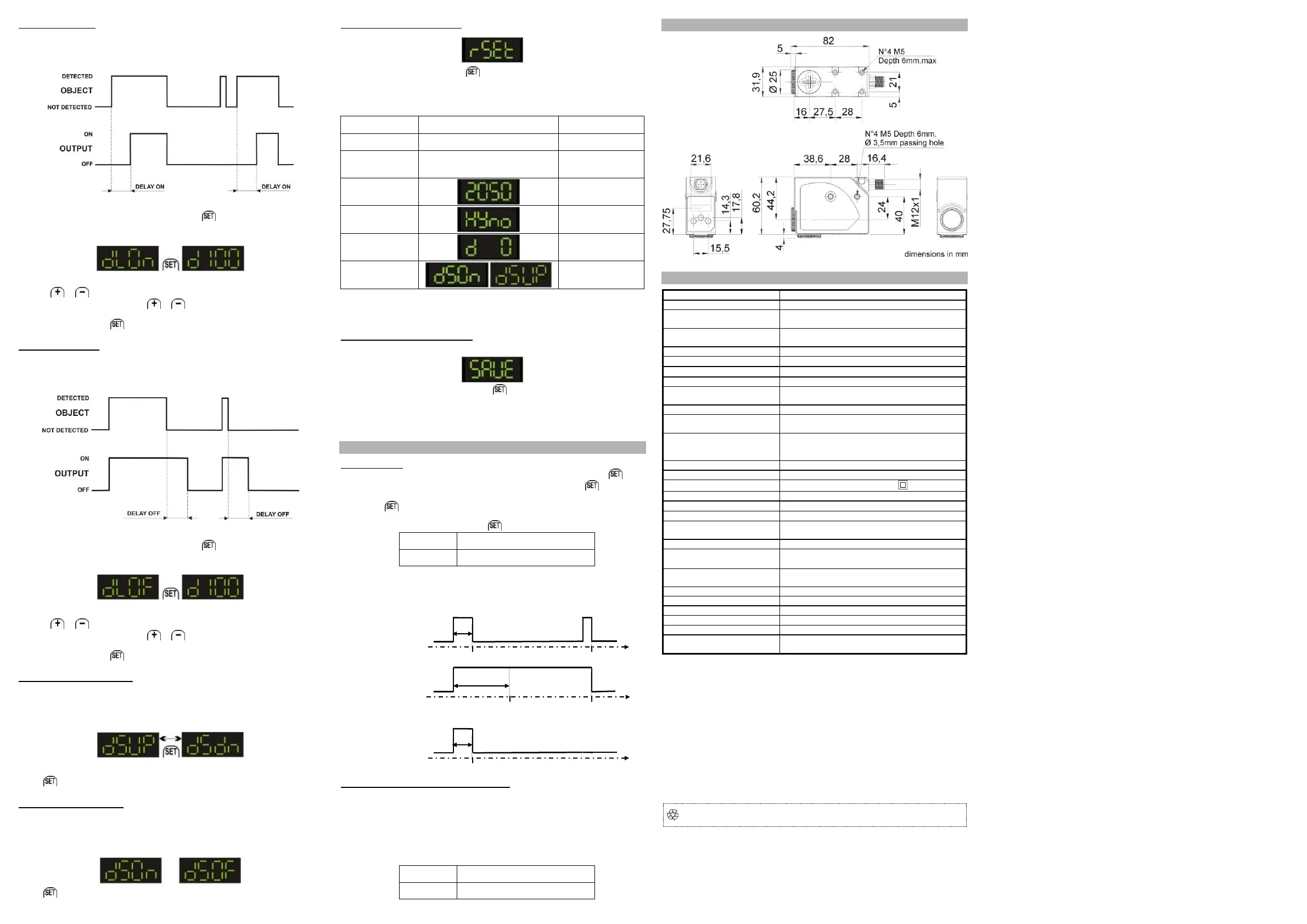
DIMENSIONS
TECHNICAL DATA
Current consumption
(output current excluded):
NPN output
30 Vdc max. (short-circuit protection)
Output saturation voltage:
16 s (MARK mode), 100us (COLOR mode)
30 kHz (MARK mode), 10KHz (COLOR mode)
4-digit display (GREEN) / OUT LED (YELLOW) /
READY LED (GREEN) / DELAY LED (GREEN)
0…100 ms programmed
default configuration without delay
Automatic in the target/background detection
selectable via wire in the dynamic detection,
selectable via MENU in the color detection
Electric shock protection:
blue ( 465 nm) / green (520 nm) / red (630 nm)
in MARK mode the selection is automatic
according to EN 60947-5-2
0.5 mm amplitude, 10 … 55 Hz frequency,
for each axis (EN60068-2-6)
11 ms (30 G) 6 shocks for each axis (EN60068-2-
27)
II 3G EX nA II T6 ;
II 3D EX tD A22 IP67 T85°C
(*) It’s available on request, PMMA plastic lens with 9mm focus.
The sensors are NOT safety devices, therefore they MUST NOT be used in the safety
control of the machines where installed.
Datalogic S.r.l.
Via S. Vitalino 13 - 40012 Calderara di Reno - Italy
Tel: +39 051 3147011 - Fax: +39 051 3147205 - www.datalogic.com
Helpful links at www.datalogic.com: Contact Us, Terms and Conditions, Support.
The warranty period for this product is 36 months. See General Terms and Conditions of Sales for
further details.
Under current Italian and European laws, Datalogic is not obliged to take care of product
disposal at the end of its life. Datalogic recommends disposing of the product in compliance with
local laws or contacting authorised waste collection centres.
© 2017 Datalogic S.p.A. and/or its affiliates ALL RIGHTS RESERVED. Without limiting the rights
under copyright, no part of this documentation may be reproduced, stored in or introduced into a
retrieval system, or transmitted in any form or by any means, or for any purpose, without the express
written permission of Datalogic S.p.A. and/or its affiliates. Datalogic and the Datalogic logo are registered
trademarks of Datalogic S.p.A. in many countries, including the U.S.A. and the E.U. All other trademarks
and brands are property of their respective owners. Datalogic reserves the right to make modifications
and improvements without prior notification.
821005670 Rev. A
Dynamic detection
(begin) start
 Loading...