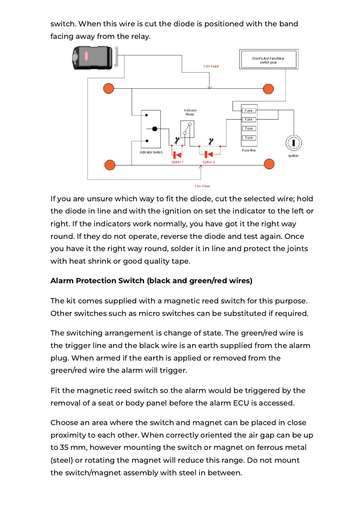
switch. When this wire is cut the diode is positioned with the band
facing away from the relay.
If you are unsure which way to t the diode, cut the selected wire; hold
the diode in line and with the ignition on set the indicator to the left or
right. If the indicators work normally, you have got it the right way
round. If they do not operate, reverse the diode and test again. Once
you have it the right way round, solder it in line and protect the joints
with heat shrink or good quality tape.
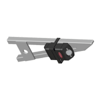
Alarm Protection Switch (black and green/red wires)
The kit comes supplied with a magnetic reed switch for this purpose.
Other switches such as micro switches can be substituted if required.
The switching arrangement is change of state. The green/red wire is
the trigger line and the black wire is an earth supplied from the alarm
plug. When armed if the earth is applied or removed from the
green/red wire the alarm will trigger.
Fit the magnetic reed switch so the alarm would be triggered by the
removal of a seat or body panel before the alarm ECU is accessed.
Choose an area where the switch and magnet can be placed in close
proximity to each other. When correctly oriented the air gap can be up
to 35 mm, however mounting the switch or magnet on ferrous metal
(steel) or rotating the magnet will reduce this range. Do not mount
the switch/magnet assembly with steel in between.
 Loading...