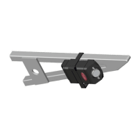
Connect the plug from the seat switch to the plug on the alarm wiring
harness. The switch has a self-adhesive backing to assist in mounting
and is also supplied with screws if this method is preferred. If using
the self-adhesive system, clean and de-grease the area thoroughly
prior to tting. Fit the magnet on the removable panel/seat adjacent
to the switch using the tting methods described above.
When correctly set; the switch should activate the alarm before the
panel is removed by 50mm. The position of the switch/magnet should
be adjusted accordingly to achieve maximum protection but to avoid
false alerts.
If more than one area is to be protected, extra magnets and switches
are available through Datatool, this is a chargeable extra. Extra
magnets may also be needed if the pillion seat is used and the
customer has a separate tailpiece. If several switches are to be used
they must be run in series, not parallel. This method also applies to
accessory loop protection where in-line connectors are positioned so
soft luggage/accessories can be protected by running an extension
wire through them and remaking the continuous trigger circuit.
The System LED Connections (orange and grey wires)
The system LED provides the rst line of defence as a visual deterrent
and provides information regarding the status of the alarm system.
Where possible agree the position for the system LED with the
customer when discussing their requirements and t it accordingly.
Do not t more than one LED, it will increase the current usage of the
system.
The LED can be installed by three methods:
In its plastic bezel shroud via a drilled 8mm hole
By an interference t of the LED into an exact size hole drilled for the
LED only (hole size 5mm)
A popular solution is to install the LED into the rear tail light or
indicator for greater visual impact however with the current trend
towards LED based rear light clusters it is very important the circuit
board on the tail light is not damaged. It is unadvisable to drill the
 Loading...