Access the wiring harness at the most suitable place(s) and identify
the wires you are going to connect to using suitable safe test
equipment. Analogue meters and bulb based test lights are low
resistance and can easily damage delicate electronic units tted to
some machines. It is advisable to use high resistance test equipment
(e.g. Digital multi-meters, LED based test lights {logic probes}, LCD
testers). If you have doubts regarding the suitability of your test
equipment, please refer to the manufacturer’s workshop manual.
Once the alarm wiring points have been selected, construct the alarm
harness accordingly. When constructing the alarm loom pay close
attention to the positioning of the alarm plugs in relation to each
other. It is advisable to temporarily connect the alarm harness to the
alarm at this stage to correctly align and tape or heat-shrink the
harness together whilst constructing the harness. Failure to do this
may mean the plugs cannot be easily connected between the alarm
and the harness.
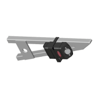
Please note the alignment of the plugs in the image, the harness
should be constructed so the at sides of the plugs are placed
together (i.e. clasps outwards).
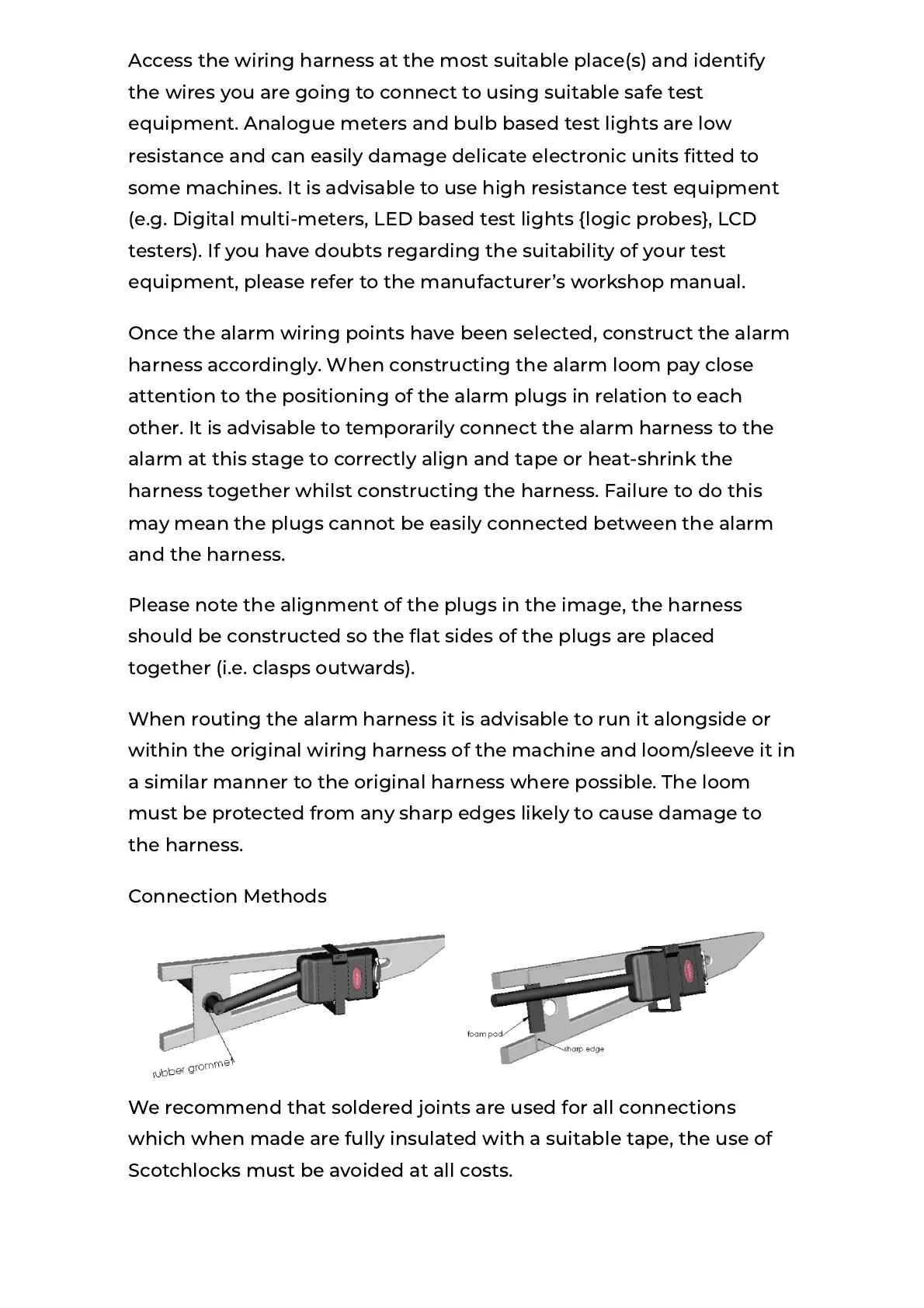
When routing the alarm harness it is advisable to run it alongside or
within the original wiring harness of the machine and loom/sleeve it in
a similar manner to the original harness where possible. The loom
must be protected from any sharp edges likely to cause damage to
the harness.
Connection Methods
We recommend that soldered joints are used for all connections
which when made are fully insulated with a suitable tape, the use of
Scotchlocks must be avoided at all costs.
 Loading...