4: Servicing
4-2 RT7000-MSOP
The front panel assembly is attached to the RT7000 with four screws and a
single ribbon cable.
Field-Level Servicing
The transceiver BITE system is designed to identify a faulty board. Feedback
is presented on the front panel display. In a matter of minutes, the radio can be
opened up, the faulty board removed and a new one inserted. For detailed
technical information, refer to the RT7000 technical manual (RT7000-MS).
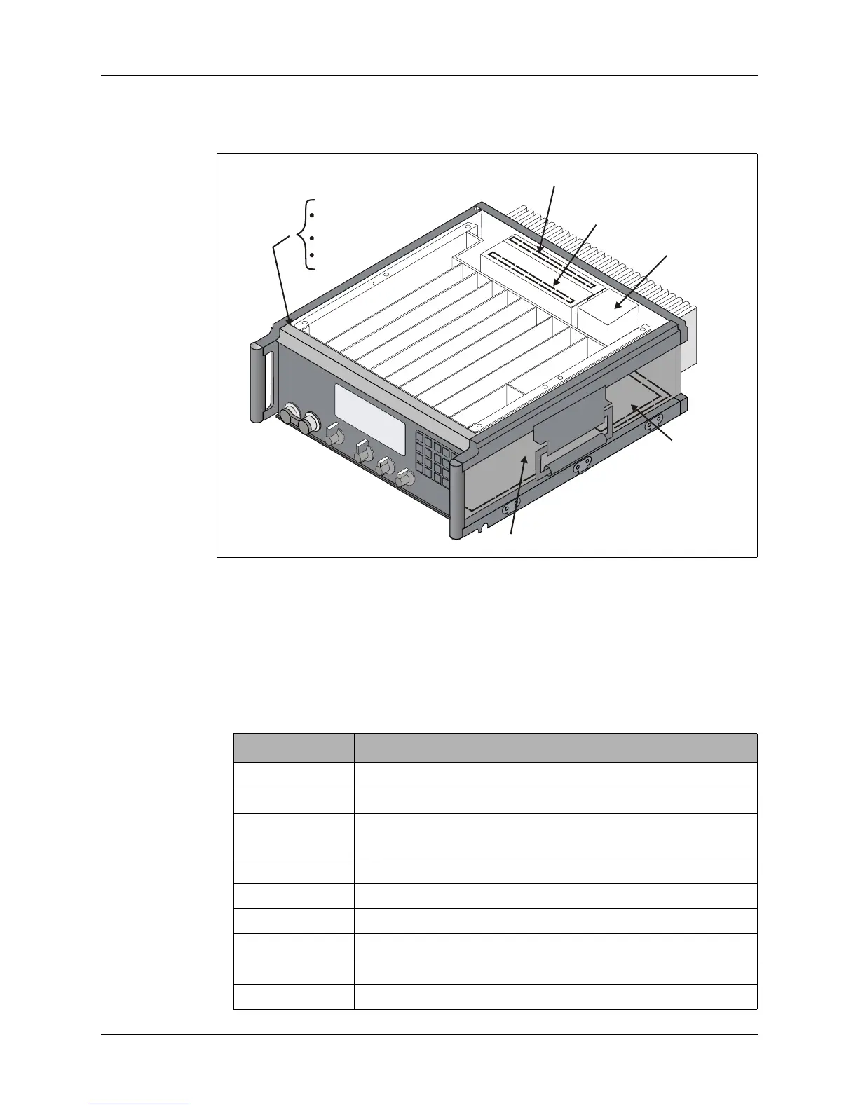
Figure 4-1. Board Locations
P
r
o
c
e
s
s
o
r
Front Panel
Processor
Display
Keypad
RF Amplifier
RF Filter
DC-DC Convertor
(28V only)
Interface/
Power Supply
M
th
r
r
A
L
E
F
S
K
/
I
S
D
N
O
P
T
2
O
P
T
1
A
u
d
i
o
7
5
M
H
z
5
M
H
z
S
y
n
t
h
e
s
i
z
e
r
N
o
i
s
e
B
l
a
n
k
e
r
R
e
fe
r
e
n
c
e
/C
o
n
tr
o
l
Part Number Description
004-01110 Front panel processor
001-00206 Reference/control board
004-12260
004-28260
RF Amplifier (12V)
RF Amplifier (28V)
001-00320 RF Filter board
004-12401 Interface/power supply
001-00600 Audio board
001-00710 75 MHz IF board
001-00800 5 MHz IF board
001-00901 Synthesizer board