EasyManua.ls Logo

Datsun 1200 - Page 38

Datsun 1200
224 pages
Print Icon
To Next Page IconTo Next Page
To Previous Page IconTo Previous Page
Loading...
5
Fuel
SY6tem
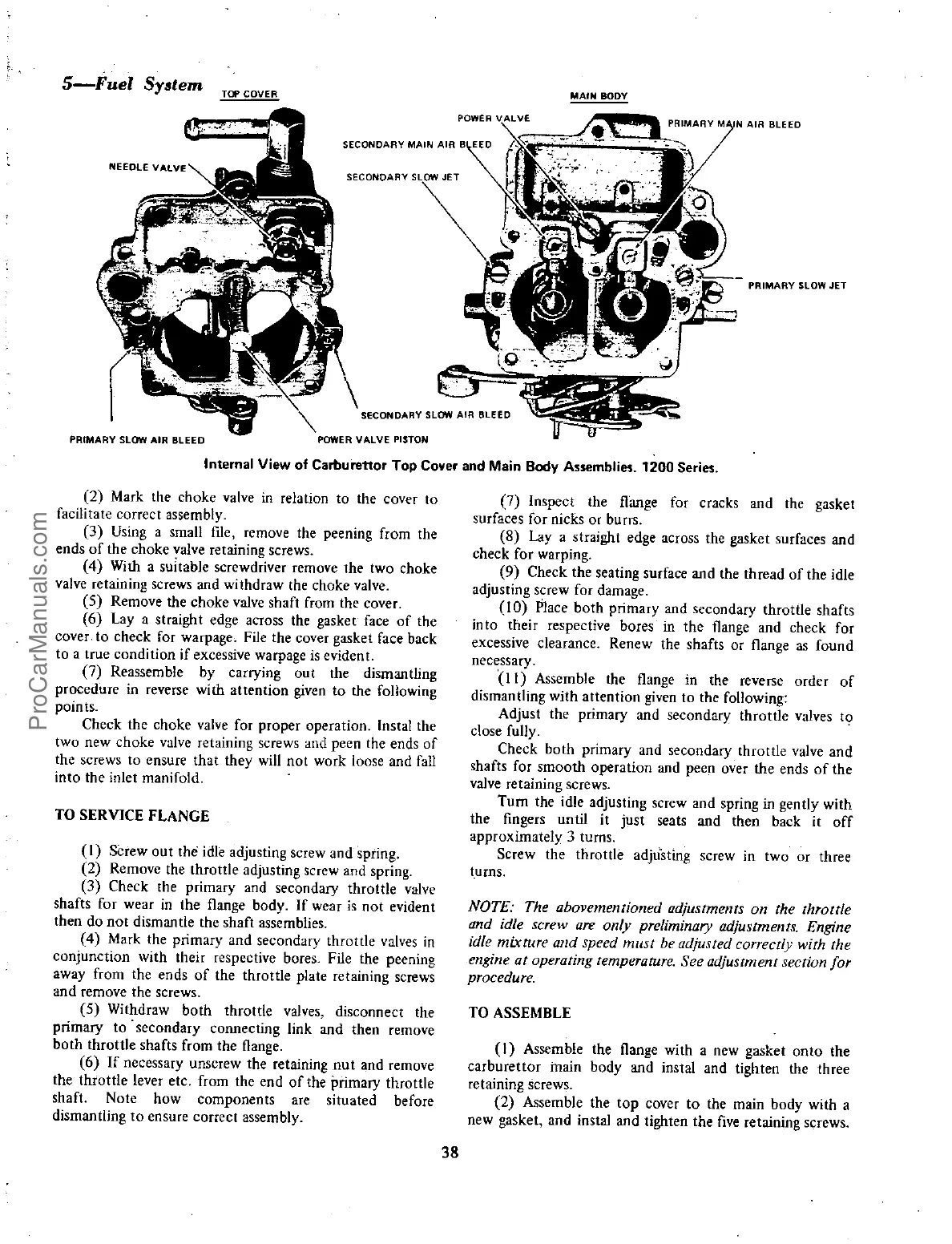
TOP
COVER
MAIN
BODY
POWER
VALVE
SECONOARY
MAIN
AIR
8
O
SECQNOARY
SLOW
JET
t
i
PRIMARY
SlOW
JET
C
O
to
J
SECONOARV
SLOW
AIR
OLEED
It
POWER
VALVE
PISTON
PRIMARY
SLOW
AIR
BLEED
Internal
View
of
Carburettor
Top
Cover
and
Main
Body
Assemblies
1200
Series
2
Mark
the
choke
valve
in
relation
to
the
cover
to
facilitate
correct
assembly
3
Using
a
small
me
remove
the
peening
from
the
ends
of
the
choke
valve
retaining
screws
4
With
a
suitable
screwdriver
remove
the
two
choke
valve
retaining
screws
and
withdraw
the
choke
valve
5
Remove
the
choke
valve
shaft
from
the
cover
6
Lay
a
straight
edge
across
the
gasket
face
of
the
cover
to
check
for
warpage
File
the
cover
gasket
face
back
to
a
true
condi
lion
if
ex
cessive
warpage
is
eviden
t
7
Reassemble
by
carrying
out
the
dismantling
procedure
in
reverse
with
attention
given
to
the
foBowing
points
Check
the
choke
valve
for
proper
operation
Instal
the
two
new
choke
valve
retaining
screws
and
peen
the
ends
of
the
screws
to
ensure
that
they
will
not
work
loose
and
fall
into
the
inlet
manifold
TO
SERVICE
FLANGE
I
Screw
out
the
idle
adjusting
screw
and
spring
2
Remove
the
throttle
adjusting
Screw
and
spring
3
Check
the
primary
and
secondary
throttle
valve
shafts
for
wear
in
the
flange
body
If
wear
is
not
evident
then
do
not
dismantle
the
shaft
assemblies
4 Mark
the
primary
and
secondary
throttle
valves
in
conjunction
with
their
respective
bores
File
the
peening
away
from
the
ends
of
the
throttle
plate
retaining
screws
and
remove
the
screws
5
Withdraw
both
throttle
valves
disconnect
the
primary
to
secondary
connecting
link
and
then
remove
both
throttle
shafts
from
the
flange
6
If
necessary
unscrew
the
retaining
nut
and
remove
the
throttle
lever
etc
from
the
end
of
the
primary
throttle
shaft
Note
how
components
a
re
situa
ted
before
dismantling
to
ensure
correct
assembly
7
Inspect
the
flange
for
cracks
and
the
gasket
surfaces
for
nicks
or
burrs
S
Lay
a
straight
edge
across
the
gasket
surfaces
and
check
for
warping
9
Check
the
seating
surface and
the
thread
of
the
idle
adjusting
screw
for
damage
IO
Place
both
primary
and
secondary
throttle
shafts
into
their
respective
bores
in
the
flange
and
check
for
excessive
clearance
Renew
the
shafts
or
flange
as
found
necessary
I
I
Assemble
the
flange
in
the
reverse
order
of
dismantling
with
attention
given
to
the
following
Adjust
the
primary
and
secondary
throttle
valves
to
close
fully
Check
both
primary
and
secondary
throttle
valve
and
shafts
for
smooth
operation
and
peen
over
the
ends
of
the
valve
retaining
screws
Turn
the
idle
adjusting
screw
and
spring
in
gently
with
the
fingers
until
it
just
seats
and
then
back
it
off
appruximately
3
turns
Screw
the
throttle
adjusting
screw
in
two
or
three
turns
NOTE
The
abovementioned
adjustments
on
the
rhraule
and idle
screw
are
olllv
preliminarY
adjustments
Engine
idle mixture
and
speed
must
be
adjusted
correct
v
with the
engine
at
operating
temperature
See
adjustment
section
for
procedure
TO
ASSEMBLE
I
Assemble
the
flange
with
a
new
gasket
onto
the
carburettor
main
body
and
instal
and
tighten
the
three
retaining
screws
2
Assemble
the
top
cover
to
the
main
body
with
a
new
gasket
and
instal
and
tighten
the
five
retaining
screWS
38
ProCarManuals.com