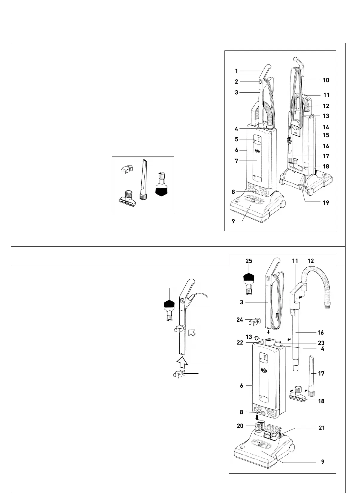
IDENTIFICATION OF PARTS
7
ASSEMBLY
1. Handle grip
2. On/Off switch
3. Handle assembly
4. Retaining ring
5. Cover release flap
6. Bag housing
7. Front cover
8. Housing release button
9. Power head with brush
10. Cable (cord)
11. Cleaning wand handle
12. Attachment hose
13. Handle catch
14. Carrying handle
15. Cable (cord) hook
16. Cleaning wand (active wand)
17. Crevice nozzle
18. Upholstery nozzle
19. Foot pedal
20. Swivel neck
21. Support lever
22. Protruding tab
23. Connecting tube
Place the power head (9) on the floor with the swiv-
el neck (20) and the support lever (21) upright. Hold
the bag housing (6) vertically and place it over the
swivel neck and support lever. Push firmly and
evenly down so that the housing release button (8)
snaps outward to its “locked” position.
Slide the dusting brush clamp (24) onto the handle
tube and tighten the screw. The handle of the dust-
ing brush (25) will now snap into the clamp.
To lock the handle (3) to the bag housing (6), turn
the handle catch (13) at the handle joint of the bag
housing (6) forward to “open” position. Then slide
the handle assembly (3) in as far as possible and
lock it in by turning the handle catch to the closed
position.
Push the black end of the attachment hose (12) into
the connecting tube (23) so that it clicks into place.
Insert the cleaning wand (16) into the swivel neck and
push the handle (11) over the protruding tab (22).
Insert crevice nozzle (17) and upholstery nozzle (18)
into the recesses in the back of the machine.
Attach dusting
brush clamp
with screw
24
25
25
18
17
24
Standard Attachments
17. Crevice nozzle
18. Upholstery nozzle
24. Dusting brush clamp
25. Dusting brush