2
Prepare the Sensor Transmitter
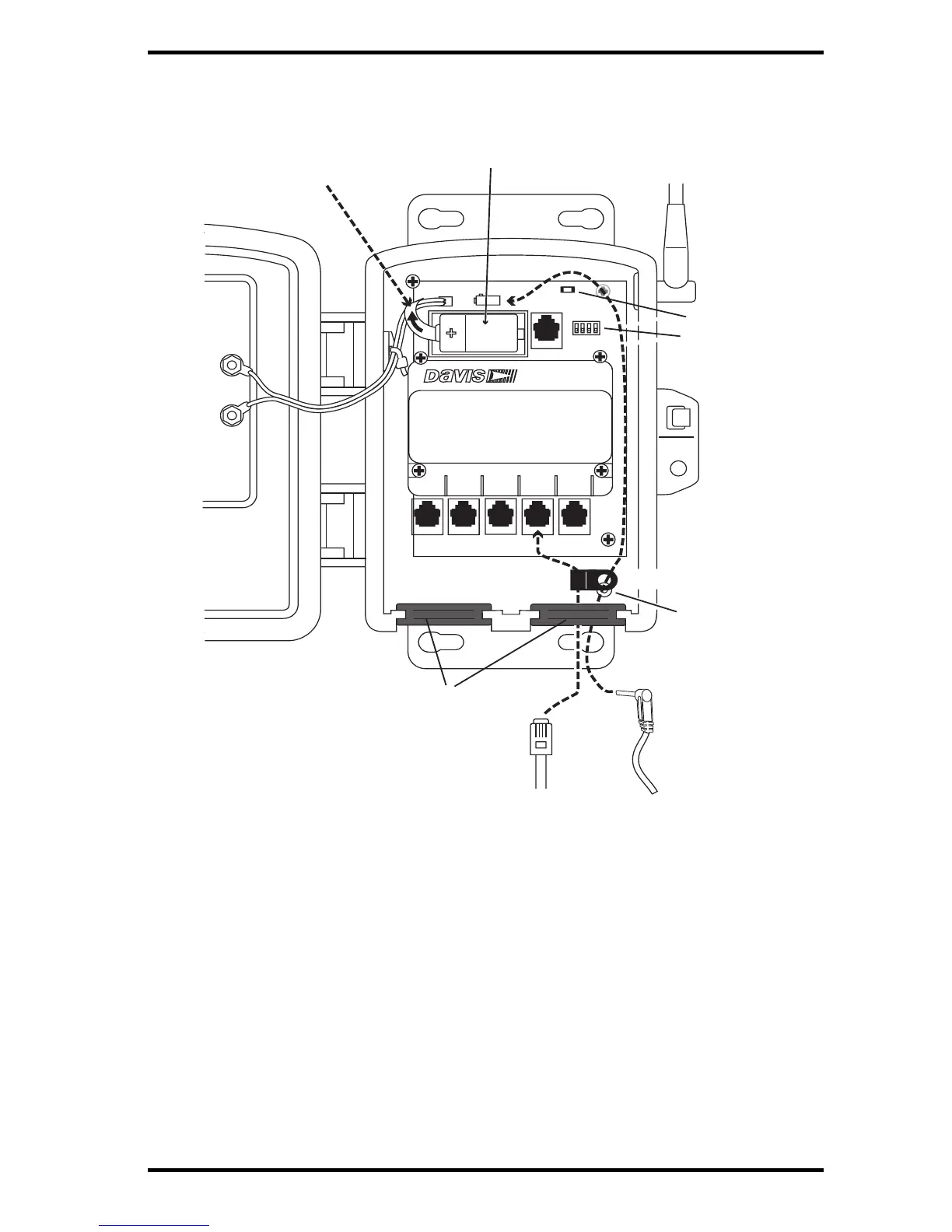
The illustration below shows the sensor interface inside the Sensor Transmitter.
1. Remove the battery pull tab and make sure the battery is firmly seated in the battey
compartment.
2. AC-powered model only: Push the power cable up through the square black grommet
on t
he bottom right. Plug it into the power jack above the battery compartment.
3. Push the ends of the sensor cables up through the square black grommet of one of the
weath
er-resistant entrances for cables.
Tip: You might find it easier to remove the grommet, thread the cable through it and then replace the
grommet.
4. Plug each sensor cable into the correct receptacle according to the label above each
receptacle. See “Installing Sensors” on page 7.
5. You may place a cable clamp over the cable (or two cables) between the grommet and
the re
ceptacle. Secure the cable clamp to the shelter by threading the provided #6
screw through the washer, then cable clamp and then screwing it into the cable clamp
mount inside the housing.