▪ The DazeBox device must be permanently connected to the electrical system through its own
differential switch. No other electrical circuits must be connected to this differential switch.
▪ The differential switch must be at least type A (30 mA tripping current) for installation in Italy. For
installation in another country of the European Community, a type B differential is required.
▪ In addition, the differential switch can be of type A for single-phase installations, while it must
necessarily be type B for three-phase installations (CEI 64-8-7 -722).
▪ The nominal current chosen must be suitable for the circuit breaker and the fuse.
The earth connection is ensured by the user's system.
The device does not have its own electric grid switch. The differential switch and / or the magnetothermal
switch of the power supply line act as a grid separation device.
The electrical connection (power supply line) must have been prepared.
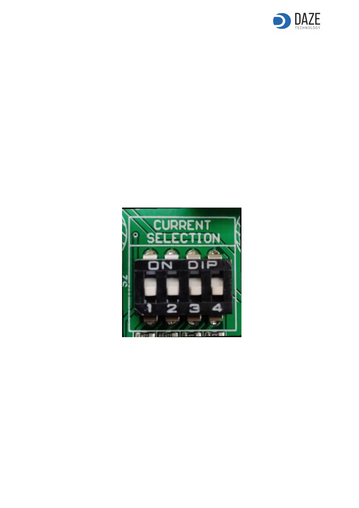
Current setting for Dazeboxes without power management.
The current is regulated by means of the selector on the board (figure 7). Each combination of the dip
switches corresponds to a specific current of use. The relative power at which the Wallbox operates is
shown in table 6.1 for both the single-phase (1F) and the three-phase (3F) wallbox.
Figure 7. Selector to adjust the current.
13
ENG - June 2020 - Rev. 1