Do you have a question about the dbx 131, 215, 231 and is the answer not in the manual?
Explains hazard symbols and basic precautions for safe operation.
Details mains lead color codes, earthing requirements, and plug safety.
Advises against water, proper cleaning, ventilation, and handling during storms.
Covers lithium battery handling and UK mains plug safety.
States product conformity to directives and EMC considerations.
How to contact dbx Customer Service for technical support and consultations.
Steps for returning a product for service, including obtaining authorization.
Details warranty validity, purchase date, and registration requirements.
Explains what the warranty covers, liability limits, and exclusions.
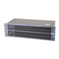
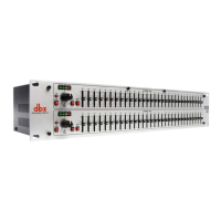
Introduces the 2-Series as advanced entry-level graphic equalizers.
Lists the main features like frequency bands, boost/cut ranges, and filters.
Items to verify in the equalizer package upon receipt.
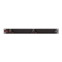
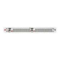
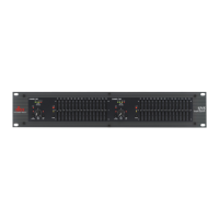
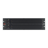
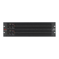
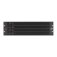
Identifies and describes the function of various controls on the front panel.
Explains input gain control, bypass switch, and bypass LED.
Details the boost/cut range selection and output level bar graph.
Describes the clip indicator and the function of frequency band slider controls.
Explains the function of the Low Cut Enable switch for the 50Hz filter.
Step-by-step guide for connecting the equalizer to audio systems.
Details the purpose and layout of connectors on the rear panel.
Advice on rack mounting, ambient temperature, and avoiding RF/EMI.
Guidelines for balanced/unbalanced connections, cable types, and hum reduction.
Details connector types, impedance, and maximum levels for inputs/outputs.
Lists bandwidth, frequency response, dynamic range, and noise specifications.
Describes function switches like EQ Bypass, Low Cut, Range, and power supply details.
Provides unit dimensions, weight, and safety certifications (CE, UL).
| Bandwidth | 1/3 Octave |
|---|---|
| Input Connectors | XLR, 1/4" TRS |
| Output Connectors | XLR, 1/4" TRS |
| Type | Graphic Equalizer |
| Maximum Input Level | +21dBu |
| Maximum Output Level | +21dBu |
| Crosstalk | -80dB |