2
IMPORTANT:
Disconnect the range and the individual shut-off valve from the gas supply piping system
during any pressure testing of that system at test pressures greater than 1/2 psig. Isolate
the range from the gas supply piping system by closing the individual manual shut-off
valve to the range during any pressure testing of the gas supply piping system at test
pressures equal to or less than 1/2 psig.
STEP 2
REPLACE COOKTOP BURNER ORIFICES AND VALVE BYPASS JETS
To replace cooktop burner orifices:
1. Remove the grates from the cooktop.
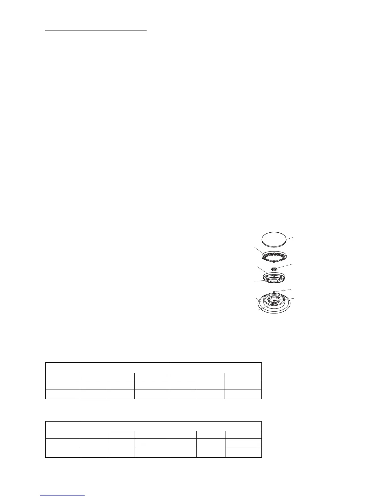
2. Remove burner caps and brass port rings (refer to diagram below).
3. Unscrew the brass nuts using a 1-1/16” socket or adjustable wrench and lift the simmer rings from the
burner bases.
4. Unscrew the brass venturis from the burner bases using a 25/32” socket.
5. Lift each burner base and disconnect the push-on wire
terminal from the spark electrode. Place the burner
base assembly in a safe place.
6. Remove the black porcelain plates under each burner
base to allow access to the orifice holders below the
cooktop panel.
7. Unscrew the orifices using an appropriately sized
conventional socket or nut driver. Use a piece of sticky
tape inside the socket to prevent the loose orifice from
falling out.
Verify that the orifice sizes in the kit match the chart sizes and
replace the burner orifices. Both the main and simmer orifices
must be changed. Do not reassemble the burners at this time.
NOTE: Gas conversion should be done before pushing the range into the cabinet.
NATURAL GAS
LOCATION MAIN LOW
SIZE MARKING RATE SIZE MARKING RATE
CENTER 1.85mm 185 17.5K Btu/hr 0.57mm P 3400 Btu/hr
OUTER 1.78mm 178 16.0K Btu/hr 0.57mm P 3400 Btu/hr
LP GAS
LOCATION MAIN LOW
SIZE MARKING RATE SIZE MARKING RATE
CENTER 1.10mm 110 15.0K Btu/hr 0.37mm G 2900 Btu/hr
OUTER 1.10mm 110 15.0K Btu/hr 0.37mm G 2900 Btu/hr
Connection: 1/2" N.P.T. - minimum 5/8" dia. metal flex line.
4mm
7mm
 Loading...