398
03
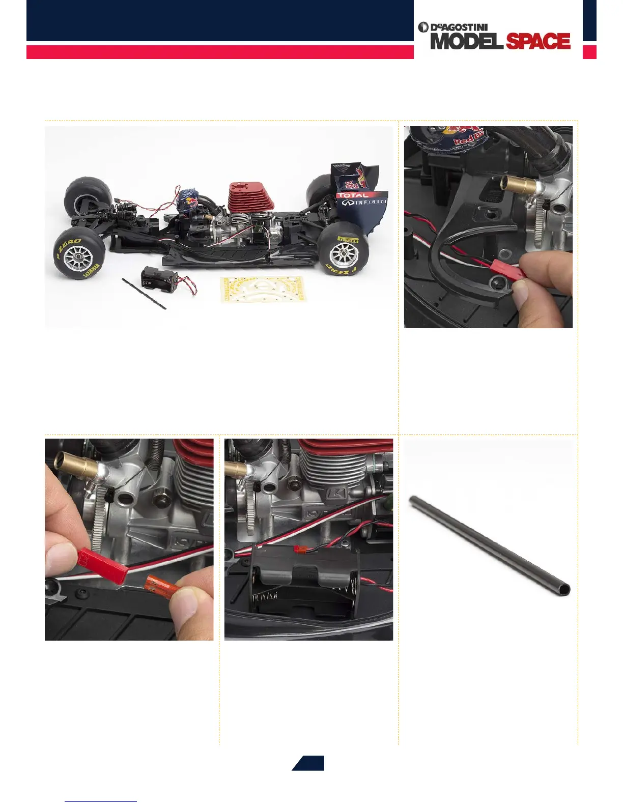
Join the red connector from Step 02
into the corresponding one at the
end of the battery box‘s cable. It will only t
in one way.
04
When the cables are connected,
place the battery box on the left
side of the chassis.
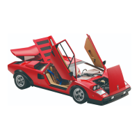
05
That completes this phase of
the assembly. Store the antenna
tube away safely until it is needed, and if
you are building your RB7 to be primarily
a display model, continue with the
following steps to apply stickers to your
RB7’s tyres.
01
Lay the parts supplied with this stage out on your work surface. If you are building
this model to be primarily a display piece, keep the sticker sheet supplied with
Stage 78 to hand, as you will be using these to decorate the inside edges of the tyres.
However, you may prefer to skip this phase if you are intending to run your model as an RC
racer, as active use is likely to cause these stickers to peel away. The antenna tube will be
tted at a later stage, so keep this safely until then.
02
First, feed the cable coming from
the front of the switch by the red
connector through to the left side of the
chassis, underneath the arc of the centre
upper plate, as shown.