EC-5 3 INSTALLING THE SENSORS
data loggers. These sensors typically come configured with stripped
and tinned (pigtail) lead wires for use with screw terminals. Refer to
your distinct logger manual for details on wiring. Our Integrator’s
Guide gives detailed instructions on connecting the EC-5 sensor to
non-Decagon loggers. Please visit www.decagon.com/support/literat
ure for the complete Integrator’s Guide.
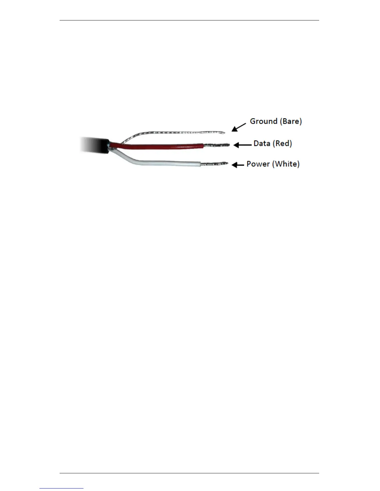
Figure 2: Pigtail End Wiring
Pigtail End Wiring
Connect the wires to the data logger as Figure 3 shows, with the
supply wire (white) connected to the excitation, the analog out wire
(red) to a analog input, the bare ground wire to ground as illustrated
in Figure 2.
Note: The acceptable range of excitation voltages is from 2.5 to 3.6
VDC.
7