Do you have a question about the Deckma Hamburg OMD-2008 and is the answer not in the manual?
Monitors inspected prior to delivery; proper identification of type/version is crucial.
Recommendation to order service exchange unit for malfunctions; return defective unit within 30 days.
Unit requires checking at IOPP Certificate renewal survey; OMD-2008 EVFC has calibration certificate.
OMD-2008 Bilge Alarm designed for 15 ppm oil-water separators, exceeding IMO requirements.
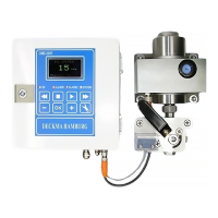
OMD-2008 available in versions with electric switchover valve and flow sensor.
OMD-2008 FC instruments have a Flow Sensor to detect low flow rates.
Optical sensor array measures light scattered/absorbed by oil; processed by microprocessor.
Unit delivered with works calibration; zero point can be re-adjusted; calibration check by manufacturer.
Two independent oil alarm circuits; adjustable set points from 1-15 ppm; alarm LEDs on front panel.
Instruments consist of Computer Unit and Measuring Cell assembly.
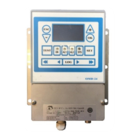
Contains display, power supply, terminals, and memory card for electronic record.
Aluminium body with stainless steel blocks; contains optics and electronics.
System uses alarm relay 2 to control pneumatic solenoid valve for overboard discharge.
EV valve can be remotely controlled via terminals 19&20.
Checks for power supply, automatic stopping device wiring, grounding, and piping connections.
Adjusting flow rate for sample and clean water streams to approx. 2 Liters per Minute.
Notes on display values, alarm indicators, and correct measurement maintenance.
Weekly tasks include flushing cell, stopping flow, cleaning cell with brush.
Memory card location and suitability for instrument life; writing only in related system.
Procedure to switch off power, stop flow, clean tube, and check reading.
Describes tests for accuracy, repeatability, and alarm conditions required for surveys.
Lists recommended spare parts to keep on board, such as a service kit.
| Brand | Deckma Hamburg |
|---|---|
| Model | OMD-2008 |
| Category | Security System |
| Language | English |