Do you have a question about the Deckma Hamburg OMD-2005 and is the answer not in the manual?
General information and operational guidelines for the monitors.
Procedure and policy for replacing defective monitor units.
Notes on unit checks, calibration certificates, and memory card handling.
Terms and conditions of the product warranty, including limitations.
How the optical sensor array measures oil droplets in the sample stream.
Key characteristics and benefits of the OMD-2005 unit.
Details on unit calibration and on-site adjustment procedures.
Information on alarm circuits, LEDs, and set point adjustments.
Checks for correct power supply connection and grounding.
Verification of all piping connections for leaks.
Procedure for checking instrument drift, repeatability, and zero adjustment.
Tests for verifying installation and alarm point settings during surveys.
Suggested spare parts to keep on board for the OMD-2005 unit.
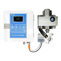
The DECKMA HAMBURG OMD-2005 is a 15ppm Bilge Alarm Unit designed for use with oil-water separator units, exceeding the International Maritime Organization (IMO) specifications for 15ppm Bilge Alarms as outlined in Resolution MEPC. 107 (49). Its primary function is to monitor the oil content in bilge water and trigger alarms or control actions when the oil concentration exceeds a set threshold.
The OMD-2005 operates on an optical sensing principle. An array of optical sensors measures a combination of light scattered and absorbed by oil droplets within the sample stream. These sensor signals are then processed by a microprocessor to produce a linearized output, indicating the oil content in parts per million (ppm).
The unit is equipped with two independent oil alarm circuits, both factory-adjusted to 15 ppm, in accordance with IMO requirements. These alarm set points can be adjusted on-site to lower values (e.g., 10 ppm or 5 ppm) using the front panel buttons. An alarm point setting above 15 ppm is not possible. When an alarm set point is exceeded, corresponding alarm indicators on the front panel illuminate, and the appropriate relays are activated.
A crucial feature is the system's response to malfunctions. In the event of an internal fault, the "System" LED on the front panel changes from a blinking green (normal operation) to a permanent red (alarm condition), and a dedicated system fault relay switches its contacts. Furthermore, if a malfunction or power supply failure occurs, all three relays (two oil alarms and one system fault) will switch to an alarm condition, ensuring a fail-safe operation.
For data logging, the OMD-2005 requires status inputs from the separator and a feedback signal from the valve position limit switch. This allows for comprehensive recording of operational data. Additionally, a 0(4) - 20 mA signal output (corresponding to 0 - 30 ppm) is available for connection to a recorder or external meter, providing continuous monitoring and historical data.
The unit's microprocessor continuously monitors the condition of its sensor components and associated electronics. This self-monitoring capability ensures that calibration accuracy is maintained over time and across various environmental conditions, contributing to the reliability of the measurements.
The OMD-2005 is designed for ease of use and installation. It features a robust construction and a watertight housing (IP 65), making it suitable for marine environments. The unit offers automatic voltage selection, accommodating power supplies from 24 V to 240 V AC or DC.
The display is a green graphic display that shows the current oil content. During startup, an initializing display is shown for approximately 15 seconds before switching to the standard measurement display. The unit is delivered with a works calibration according to IMO requirements, and its "Zero" point is also factory calibrated. This zero point can be re-adjusted on site using clean water in the programming mode. However, a full calibration is not permitted on-site and must be performed by the manufacturer or authorized personnel in accordance with IMO regulations.
The programming mode, accessible via the front panel buttons, allows for modification of alarm set points, time delays, and the signal output type (0-20 mA or 4-20 mA). The time delays for Alarm 1 (for annunciation) and Alarm 2 (for control purposes) can be adjusted independently, providing flexibility in system integration. The unit also provides a pilot voltage output (fused by Fuse F1) at terminals 4&5, which can be used to supply additional external circuitry such as alarm lamps or electrical valves. It's important to note that this pilot voltage is intended for alarm purposes only and should not be used for high-load devices like motors or heaters.
The OMD-2005 incorporates a memory card for data logging. This card is designed to store data for at least 18 months, fulfilling MEPC 107(49) requirements. When the card is full, the oldest entries are overwritten, eliminating the need for frequent replacement. The memory card is linked to the specific system, meaning it can be read in other OMD-2005 units but can only be written to in its original system. If no memory card is present or a card from another system is inserted, the unit will enter an alarm condition, ensuring data integrity.
Maintenance of the OMD-2005 is designed to be straightforward and minimal. Weekly maintenance involves flushing the cell with oil-free water, isolating the instrument from both sample and oil-free water supplies, and then unscrewing and removing the cell cap. A suitable Cell Cleaning brush (Art. No. 30102) is used to clean the cell with upwards and downwards motions several times. After cleaning, the cell cap is replaced, and the oil-free water supply is reconnected to flush the instrument for a few minutes. The display should then show an oil content of 0 to 2 ppm. If not, the cleaning procedure should be repeated.
A key maintenance item is the desiccator (Fig. 1, Pos. 11), which ensures humidity inside the measuring cell remains below 40%. This prevents condensation on the cell glass tube, which could lead to inaccurate measurements and damage to the electronics. The desiccator's color indicates its activity: blue signifies an active absorber, while light blue or white indicates it needs replacement. Replacement is simple and does not require opening the instrument; the old desiccator is unscrewed from the front panel and replaced with a new one. The protection cap of the spare unit can be used as a tool for this.
In cases of high readings with clean water, indicating internal coating of the glass tube, a more thorough cleaning procedure is recommended. This involves removing the desiccator to check the glass tube's cleanliness. If a brown coating (potentially iron oxide) is visible, citric acid, lemon juice, or vinegar can be filled into the glass tube and left overnight to dissolve the dirt before using the cleaning brush. This process may need to be repeated multiple times for at least 12 hours, depending on the coating's thickness. Slightly abrasive cleaning powder or toothpaste can also assist in cleaning.
The OMD-2005 is electronically sealed to prevent unauthorized access to calibration settings, ensuring compliance with MEPC.107(49) regulations regarding instrument drift, repeatability, and zero adjustment. Only the manufacturer or authorized personnel with specialized tools can access and change the calibration. For routine checks aboard ship, a zero check procedure is provided which also confirms the instrument's drift within specifications. A function test can be performed by changing the position of the 3-way valve to the clean water position, which should trigger an alarm, confirming correct installation and operation.
| Range: | 0 – 30 ppm, Trend up to 50 ppm |
|---|---|
| Accuracy | According IMO MEPC. 107(49) |
| Linearity | Up to 30 ppm better than ± 2 % |
| c Sample Flow: | Approx. 0, 1 - 4 l/min depend. to pressure |
| Display | m Green Graphic Display |
| Power Supply: | o 24 V – 240 V AC or DC Automatic Voltage Selection |
| Consumption: | < 15 VA |
| Alarm Points 1 + 2: | c . Adjustable between 1 - 15 ppm (Works adjustment 15 ppm) |
| Alarm 1 Operating Delay: (for annunciation purpose) | k Adjustable between 1 – 540 sec. (Works adjustment 2 sec) |
| Alarm 2 Operating Delay: (for control purposes) | c Adjustable between 1 – 10 sec. (Works adjustment 10 sec) |
| System Fault Alarm: | e Red LED |
| h Alarm Contact Rating: | Potential free 1 pole change over contacts, 3 A / 240 V |
| Alarm Indication: | Red LED's |
| k Sample Water Pressure: | 0, 1 – 10 bar |
| Ambient Temperature: | + 1 to + 55° C |
| o Sample Water Temperature: | + 1 to + 65° C |
| Degree of Protection: | IP 65 |
| C Output Signal: | 0 – 20 mA or 4 – 20 mA for 0-30 ppm reversible, ext. Load < 150 Ω |
| Pipe Connections: | R ¼" Female |
| Roll: | Up to 45° |
| Size (over all): | 360 mm W x 240 mm H x 100 mm D |
|---|---|
| Weight: | 7, 3 kg |