Influence of the parameter setting CT.TEL on the I.TEL: contact
CT.TEL I.TEL:
C contact closed C contact open
OPEN ANTIFR
The mode selected on the boiler is active. The antifreeze mode is active on all boiler circuits.
0/1 A
The antifreeze mode is active on the circuit
concerned.
The mode selected on the circuit is active.
0/1 B
The antifreeze mode is active on the circuit
concerned.
The mode selected on the circuit is active.
0/1 A+B
The antifreeze mode is active on the circuits
concerned
The mode selected on the circuits is active
0/1 C
The antifreeze mode is active on the circuit
concerned.
The mode selected on the circuit is active.
0/1 A+C
The antifreeze mode is active on the circuits
concerned
The mode selected on the circuits is active
0/1 B+C
The antifreeze mode is active on the circuits
concerned
The mode selected on the circuits is active
0/1 A+B+C
The antifreeze mode is active on the circuits
concerned
The mode selected on the circuits is active
0/1 DHW
The antifreeze mode is active for the DHW circuit. The mode selected on the DHW circuit is active.
0/1 A+DHW
The antifreeze mode is active on the circuits
concerned
The mode selected on the circuits is active
0/1 B+DHW
The antifreeze mode is active on the circuits
concerned
The mode selected on the circuits is active
0/1 A+B+DHW
The antifreeze mode is active on the circuits
concerned
The mode selected on the circuits is active
0/1 C+DHW
The antifreeze mode is active on the circuits
concerned
The mode selected on the circuits is active
0/1 A+C+DHW
The antifreeze mode is active on the circuits
concerned
The mode selected on the circuits is active
0/1 B+C+DHW
The antifreeze mode is active on the circuits
concerned
The mode selected on the circuits is active
0/1 AUX
4 The MAUX outlet on the connection terminal
block is not active.
4 The boiler operates with a set point
temperature as a function of the outside
temperature.
4 The MAUX outlet on the connection terminal
block is active.
4 The boiler operates at a set point temperature
equal to BOILER MAX.
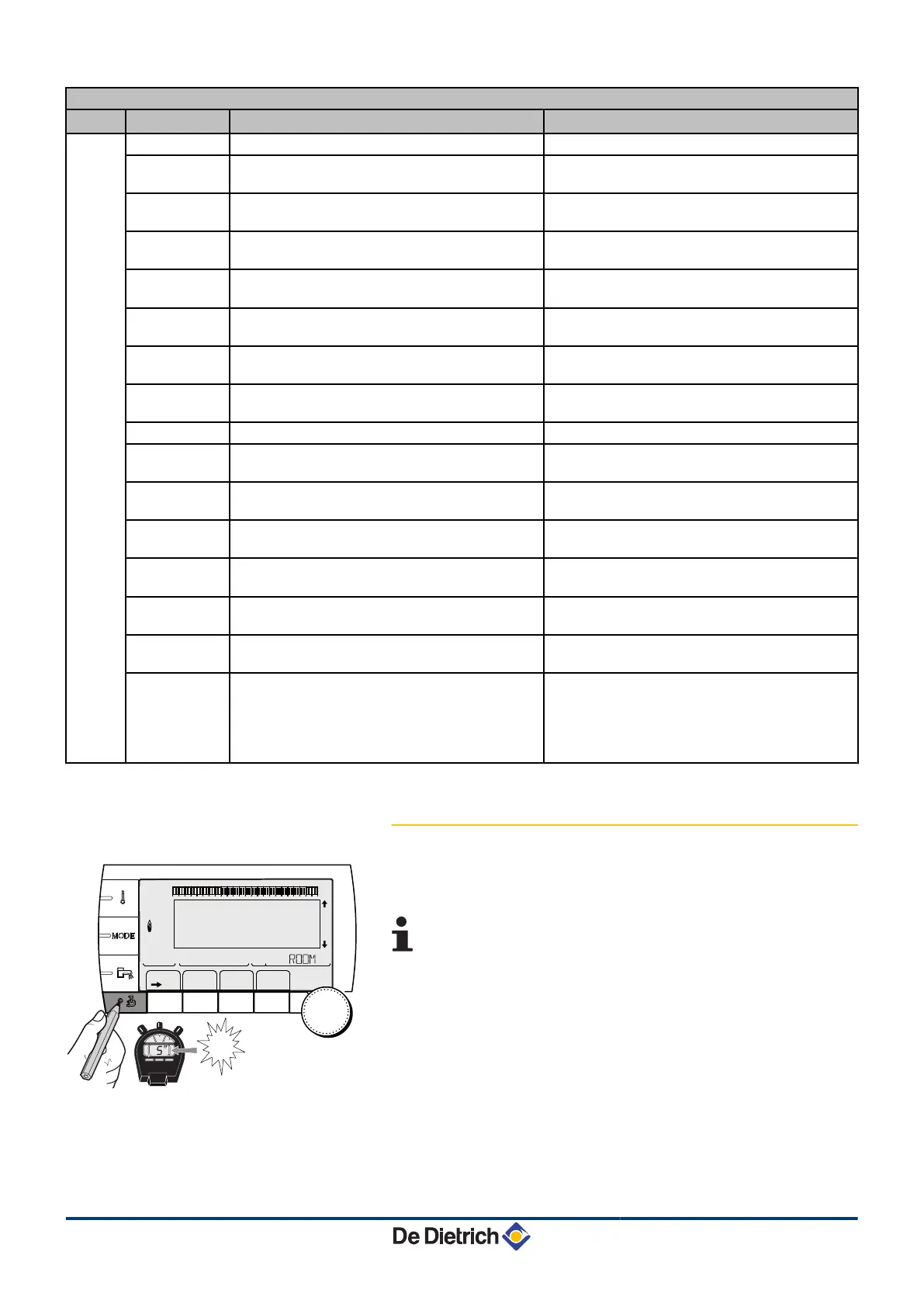
5.5.3. Naming the circuits and generators
1. Access the installer level: Press key
-
for around 5 seconds.
2. Select the menu #NAMES OF THE CIRCUITS.
4
Turn the rotary button to scroll through the menus or
modify a value.
4 Press the rotary button to access the selected menu
or confirm a value modification.
¼
For a detailed explanation of menu browsing, refer
to the chapter: "Browsing in the menus", page 62
1
1
2
2
r
c
STD
(
'
t
v
0 2 4 6 8 10 12 14 16 18 22 2420
p
b
AUTO
x
c
r
j
M
g
m
SUNDAY 11:45
5
"
TEMP.: 68°
C002235-F-04
5. Commissioning MCA 35
74
15/06/12 - 300022160-001-01
 Loading...