EasyManua.ls Logo

Deep Sea Electronics Plc 555

Deep Sea Electronics Plc 555
61 pages
To Next Page IconTo Next Page
Loading...
Deep Sea Electronics Plc
GenComm Communications Protocol for use with 550,555,
5210 and 5220 controllers.
Author - A.D.Manton
Author of GenComm V1.29 - G.Middleton
深圳市威华特科技有限公司                  
www.wellfut.com 0755-27153030 13537855559

Table of Contents

Question and Answer IconNeed help?

Do you have a question about the Deep Sea Electronics Plc 555 and is the answer not in the manual?

Deep Sea Electronics Plc 555 Specifications

General IconGeneral
DC Supply8 V to 35 V continuous
Magnetic Input Frequency10, 000 Hz (max)
Operating Temperature Range-30°C to +70°C
Magnetic Input Range6-35V AC
Protection RatingIP65
Cranking DropoutsAble to survive 0 V for 50 mS, providing supply was at least 10 V before dropout. This is critical and achieved by internal capacitors. Dropouts are particularly serious during engine cranking.

Summary

Introduction

Modbus Functions Overview

Function 3 - Read Multiple Registers

Details the Modbus Function 3 for reading multiple registers, including query and response formats.

Function 16 - Write Multiple Registers

Details the Modbus Function 16 for writing multiple registers, including query and response formats.

Exception Response Handling

Explains how Modbus functions can return exception responses and their meanings.

Modbus Registers Definition

GenComm Page 0: Communications Status

GenComm Page 1: Communications Settings

GenComm Page 2: Modem Settings

GenComm Page 3: Generating Set Status Information

Control Mode Descriptions

Details the different control modes (Stop, Auto, Manual, Test, User Config) for generator operation.

GenComm Page 4: Basic Instrumentation

GenComm Page 6: Derived Instrumentation

GenComm Page 7: Accumulated Instrumentation

GenComm Page 8: Alarm Conditions

Interrogating Alarm Status

Explains how to poll status registers to identify active alarms and locate alarm text strings.

GenComm Page 11: Diagnostic - General

Module Control Button Functions

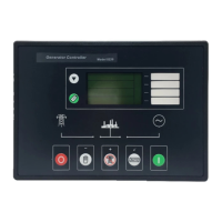
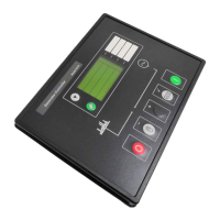
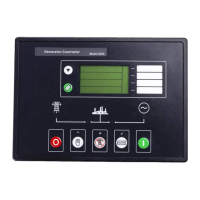
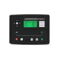
Lists the control buttons and their corresponding function numbers for module operation.

GenComm Page 12: Diagnostic - Digital Inputs

GenComm Page 13: Diagnostic - Digital Outputs

GenComm Page 14: Diagnostic - LEDs

GenComm Page 16: Control Registers

System Control Key Functions

Lists system control functions and their corresponding keys for executing commands.

Related product manuals