Do you have a question about the Deep Sea Electronics Plc 5210 and is the answer not in the manual?
Clarifies the notation and symbols used throughout the manual for clear understanding.
Describes how to activate and the sequence of events in automatic mode.
Explains manual control, start sequence, and operation of the generator.
Details non-critical alarm conditions that alert the operator to undesirable states.
Pre-warns the operator of potentially serious alarm conditions before shutdown.
Indicates generator output current exceeding a pre-set trip level.
Describes latching shutdowns that stop the generator and require fault clearing.
Details shutdown condition for prolonged high generator output current.
Explains controlled stops due to electrical faults, including cooling down.
Shows examples of instrument, status, and user-defined displays on the LCD.
Details the different zones of the LCD display and their functions.
Explains how to scroll through and display various engine parameters.
Describes how to interpret J1939 CANbus alarm messages.
Details how to access and review logged shutdown and electrical trip alarms.
Explains the meaning of common alarm and status indicators on the LCD.
Describes the function of each control button and operating mode.
Step-by-step guide to enter the front panel configuration editor mode.
Details how to edit analogue parameters and save changes via the front panel.
Explains how to adjust the module's internal clock and calendar.
Specifies the required panel cutout size for mounting the module.
Advises on operating temperature and ventilation for the module.
Provides the physical dimensions of the DSE 5210 module.
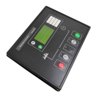
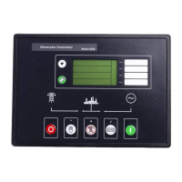
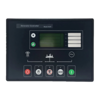
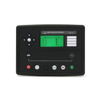
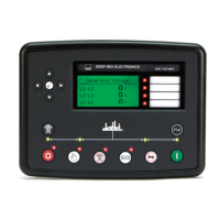
Illustrates the layout of controls and indicators on the front panel.
Shows the arrangement of connectors and terminals on the rear panel.
Details pin assignments and recommended cable sizes for various connectors.
Specific pinout and notes for the 8-way Plug A.
Specific pinout and notes for the 11-way Plug B.
Pinout for the optional 3-way Plug C used with J1939 controllers.
Pinout for the optional 4-way Plug D used with RS485 controllers.
Pinout for the 4-way Plug F for Generator Voltage Sensing.
Pinout for the 5-way Plug G for Current Transformer connections.
Pinout for the 4-way Plug H for Sender Inputs.
Details the connector for PC configuration via the 810 interface.
Describes the connector for connecting expansion modules.
Explains the function of each pin for the main connectors.
Detailed functions for each pin of Plug A.
Detailed functions for each pin of Plug B.
Pin functions for optional Plug C used with J1939 controllers.
Pin functions for optional Plug D used with RS485 controllers.
Pin functions for Plug F (Generator Voltage Sensing).
Pin functions for Plug G (Current Transformer connections).
Pin functions for Plug H (Sender Inputs).
Lists part numbers for ordering additional connector plugs from DSE.
Describes connections between the 52xx controller and J1939 enabled controllers.
Details electrical connections for Cummins ISB/ISBE engines via J1939.
Details electrical connections for John Deere engines via J1939.
Details electrical connections for Perkins 2800 Series engines via J1939.
Details electrical connections for Scania S6 engines via J1939.
Details electrical connections for Volvo TAD12 engines via J1939.
Outlines essential checks to be made before starting the system.
Identifies the function of each push button on the module's front panel.
Explains the icons used for status and measurement units on the LCD.
Describes the icons used to indicate different types of alarms.
Details wiring configurations for different AC system types.
Wiring diagram for a 3-phase, 3-wire system.
Wiring diagram for a 1-phase, 2-wire system.
Wiring diagram for a 2-phase, 3-wire system.
Graph showing typical Inverse Definite Minimum Time (IDMT) tripping curves.
Provides guidance on wiring oil pressure, coolant, and fuel level senders.
Specific recommendations for wiring earth return type senders.
Specific recommendations for wiring insulated return type senders.
Explains how fuel level senders work and tank shape considerations.
Describes the module's capability to receive engine data via J1939 CANbus.
Illustrates an example connection diagram for the 5210 to an engine CANbus.
Details the PC software and interface module for configuration.
Describes methods for expanding the module's output capabilities.
Explains the 157 relay expansion module for additional relays.
Explains the 548 LED expansion module for remote LED indication.
Describes options for increasing the number of monitored inputs.
Explains how the 5210 interacts with mains monitoring and ATS controllers.
Discusses upgrading to a 5220 controller for auto mains failure functions.
| Brand | Deep Sea Electronics Plc |
|---|---|
| Model | 5210 |
| Category | Controller |
| Language | English |