DSE Model 5210 Automatic Start Engine Management and Instrumentation System Operators Manual
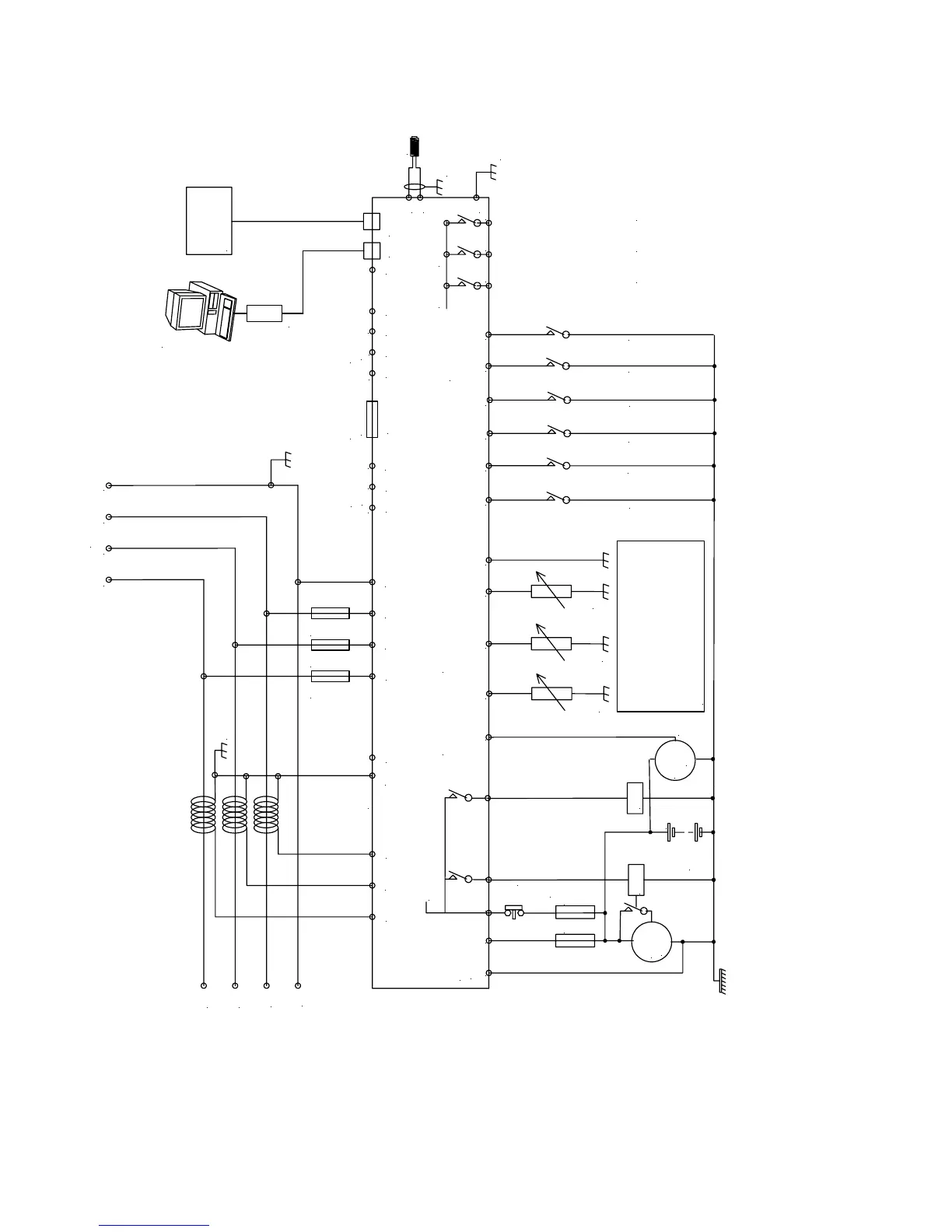
12 TYPICAL WIRING DIAGRAM
To plant supply +ve
Crank
Starter
motor
Battery
Charge
alt.
WL
F
F
Fuel
Emergency
stop
internal emergency stop
Configurable auxiliary input 1
Configurable auxiliary input 2
Configurable auxiliary input 3
Configurable auxiliary input 4
Configurable auxiliary input 5
L1
L2
L3
N
L
AD
F2A F2A F2A
+
Supply for
controller
L1 L2 L3 N
These ground connections must be
on the engine block and must be
a sound electrical connection
to the sender bodies.
The wire to terminal 47 must not
be used to provide a ground
connection to any other device.
Coolant temp. sender
Fuel level sender
RS485
Optional
9 way D
Optional
RS232
5210 controller
Optional
CanBus
Not connected
Output expansion
157 relay board
or
548 annunciator
5200 series
configuration software
810 interface
810
157/548
Ground screen
at one end onl
Functional
Earth
MPU
17
18
16
6 7 8
1413
12
1110
474645
Oil pressure sender
449
4
531 2
39
40
41
42
43
CT
common
CT
Earth
35
36 37 38
20 21
22
23 24 25 26
Configurable auxiliary input 6
15
Configurable auxiliary output 1
Configurable auxiliary output 2
Configurable auxiliary output 3
SCR A
BCOM H
L
Not connected
Not connected
19
5210 OPERATING MANUAL ISSUE 2 21/05/2003 AM
42